Introduction to Logickin’s Logical Logbook
Wanna know what's behind the Pong?
Or the details of VOXCOM1610?
It is no longer a Myth!
Introducing, The Logickin’s Logical Logbook (3xLog)! An informal documentation for implementing logic circuit using SunVox! In this tutorial, you will learn not only the SunVox implementation, but also the real world of Digital Logic, Computer Architecture, or even Computer Algorithms. We start by building simple components like the logic gates and simple arithmetic modules, for the fundamental idea of logic processing in SunVox. Then we will move on the memory circuits like latches and flip flops, to help you to build a state machine. After that, I will move on to the more complex circuit like ALU, Registers, Graphics, algorithms, etc, and a bit of story about how I build a fully functional 16bit computer, to guide you how to achieve such a complex project.
After this tutorial, you will have enough knowledge to build some logic circuits, from implementing some interesting behaviors for your modules, to making your own interactive game, with only using SunVox Modules.
I hoped that this material can makes SunVox not only a power Music Tracker, but also a fun, educational learning material for anyone who want to learning how computers work.
But... why do a remaster from the original Logbook?
Some might ask what happened to my original 3xLog, and why I had stopped update it for a really long time. Since the Graphic Chapter, I had a lot of struggle on writing the tutorial.
The first problem was about the performance of Wordpress. For some reason, once the editor has couple of paragraph blocks with one or two image, the editor lagged so badly to a point editing is painfully slow, and moving the order of an image takes a few tens of seconds which is ridiculous. Owing to this issue, I gave up expending some of the topic
The second issue is the sustainability. This logbook only works when I use my current website theme, using circuit.js with hardcoded location, paired with a specific commercial, close-sourced plugin, without any backups. This is really dangerous, as if I have a style change to my website, or change the domain name, or my website has shutdown, the whole log book will be vanished from the world, losing most of the interesting hacks and tricks to make some "smart" SunVox modules.
Hence, for these problems, I decided to use my favorite guide book format, the rust mdbook, which it provides a clean style to work with, while the markdown format can let me writing down all the SunVox knowledge within a couple of minutes, using my ide of choice. In addition, I can make a backup using any git repositories to store my logbook off-site, so that not only others can expend the book with pull-requests and fix any error with issues, but also keeping it safe from being destroyed if my blog has shutdown in various reason.
hmmm... I got some issue...
Despite being a former Electronic and Computer Engineering student, and currently a software developer, I might still make mistakes on my tutorial, so please help me find any mistakes and point that out on the issue tab of my repository for a correction. If you have any suggestion, please tell me about it as well, so that to further improve this tutorial.

How To...
Before reading, I would recommended the following settings to have the best experience:
Due to how mdbook spacing works, half of the space are used for padding, meaning that all of the content will be located at the middle of the screen; this can be problematic for some of my original image which they can be too small for reading. Zooming will solve most of the problem; you may also view the images by right clicking into a new tab which will show the full resolution. I have also attached the examples so that you can have a deeper look on how all the logical structure are achieved.
Understand The Fundamentals
In this chapter, you will know the most commonly used module for digital signal processing and how to use them to build simple combinational logic circuits.
After you have learnt this chapter, you can do most of the calculation in SunVox, such as selecting a specific signal path, and calculate with math expression, which covers most of the knowledge you would need for designing you module with special behavior.
At the end of the chapter, I will post all of the modules you have gone through, so you don’t need to re-invent the wheel and you can do logic calculation out of the box. The related riddles are also provided once I have more and less completed the logbook.
Commonly Used Modules For Processing Logic
Unlike composing a track or designing sounds, you don't need any fancy modules like FMX, Accipiter or CaRaCaRa to make logic circuits, but the following rather basic modules:
Amplifier

Normally, you use amplifier in SunVox projects mostly because you want to change the loudness of a signal, or to change the panning of the sound, so you can make the track sounds wider. In logic processing, amplifiers play a crucial role, due to its simplicity and its features. Here is a list of useful features in amplifiers:
- DC offset: Generates a perfect 8 bit DC signal.
- Inverse: Invert an in coming signal
- Absolute: Change negative signal into positive.
- Balance, stereo width and gain: Extract regulated version of the left or right signal
These controls are useful because you can build logic gates like “or” and “not”, by combining the three controller mentioned above. You can use it for simple calculation like adding two incoming signal or to multiple/divide the input with a constant. You can combine two signal into one by storing them in left and right channel separately, while you can also split the channels by selecting the channel; setting the width to none; and doubling the gain, so you can create a more compact design.
Distortion
Distortion is an other commonly used module in the realm of logic processing. You only need to use two of the controllers from the module:
- Type: Set the type of distortions
- Bit depth: Quantize the input to the nearest bit
Distortion actually only has few uses, but it executes the job fantastically. The first common uses for distortion is used for negative detection, with the bit depth set to 1. Another application is to check the odd parity of a signal, by setting the type to overflow. The last thing you would use distortion is to prevent the signal getting out of bound, by using different types, that may handy for generate graphics.
Modulator

At first glance, it doesn’t seem to have many controls. All you can change are the modulation type, the volume and the channels. However, its amplitude modulation mode is versatile, which you can use it for building some and gates, controlling the route of the signal, or even doing multiplication.
Delay

Obviously, delay module is used for… well, delaying signals. It offers quite a few useful controllers, making it more than just a delay:
- Delay L/R: To set the delay time
- Channels: Set the signal to stereo or mono
- Delay unit: Change the unit of the delay time. (Like Hz, ms, sample)
- Inverse: Invert the wet signal of delay.
- Feedback: Set the amount of the output signal loops back to input.
Thanks to the inverse function, delay can also be a mono-stable circuit to send pulses to other components. In addition, the newly introduced feedback makes delay also acting as a memory storage which is handy for storing temporary data.
Feedback

If you are a mindustry player, you know there is a component called the Router. The routers play in a crucial role where the items need to be distributed in multiple conveyor belts; however, if you chain the routers, they pass the item back to the previous router, clogging the whole system resulting in a lower efficiency.
The reason why I point out mindustry because Feedback modules is similar to Routers, which is a necessary evil; you have to use it when you want to form a feedback loop in your system for building a stateful system, but the module itself has a 20ms delay, so you can't chain too many of them; otherwise, your logic circuit will be high in latency. You have to use at least one pair of them at best, so normally your contraption will never soar beyond 50Hz. Use it wisely
Soundtctl

This module converts your incoming audio signal into control signal. Although it doesn't offer audio rate performance, it is a great module if you want more than two inputs for your specific modules (e.g. 16 bit Ram bank with indexing and enables), so you can reserve the audio input for time critical parameters like clock signal or data bus.
Multisynth
Multisynth duplicates midi signal to the ancient output modules, but it is not useful on its own if we talk about logic processing, unless you pair it with the following:
Velocity2ctl
This is an underrated module which its original purpose is to detect incoming velocity of a midi note and converts it into controller value, which is rarely used for making music unless you want to design a module with velocity sensitivity for some parameters other than the volume. In logic processing of SunVox, this is a handy module for building memory block with loosely instantaneous response, and you will know how to make one for the upcoming tutorials.
Ctl2note
The two modules above will be useless if you can't use Ctl2note because this is the only module that can convert your controller signal into midi signal by manipulating the pitch, velocity and the state of the module, to trigger any midi based flip flops.
Metamodule
The Inception of SunVox. This over-powered module can loads another SunVox instance. Besides user defined controllers, you may also need the following controls:
- Input Module: Change which module will receive an input.
- Play patterns: Have an option to do project playback.
- BPM and TPL: Change the speed of the project playback.
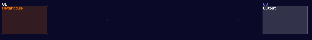
There are lot of applications for metamodules. At first, you can use it to simplify the structure of your logic machine, making it more readable. You can reuse the metamodule by copy and paste, so you can scale a project easily with the commonly used logic. Another use for metamodule is to build a source block, that you can enable project play back to simulate input switch and clock. If this module didn't exist in the first place, VOXCOM 1610 and pong would not exist.
Conclusion
The rule of the modules above make SunVox turing complete. In theory, you can compute anything only with these modules if you give it enough time and memory. Obviously, there are more modules for building logical structure in a more efficient way; I will introduce them in the later section when they are needed.
Module Conventions and Practices
Overview
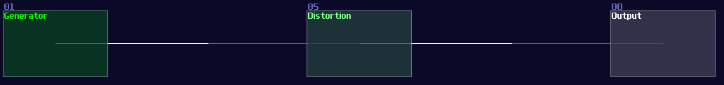
SunVox can be quite chaotic based on your practice, and no one can prevent you from being the chaotic evil:
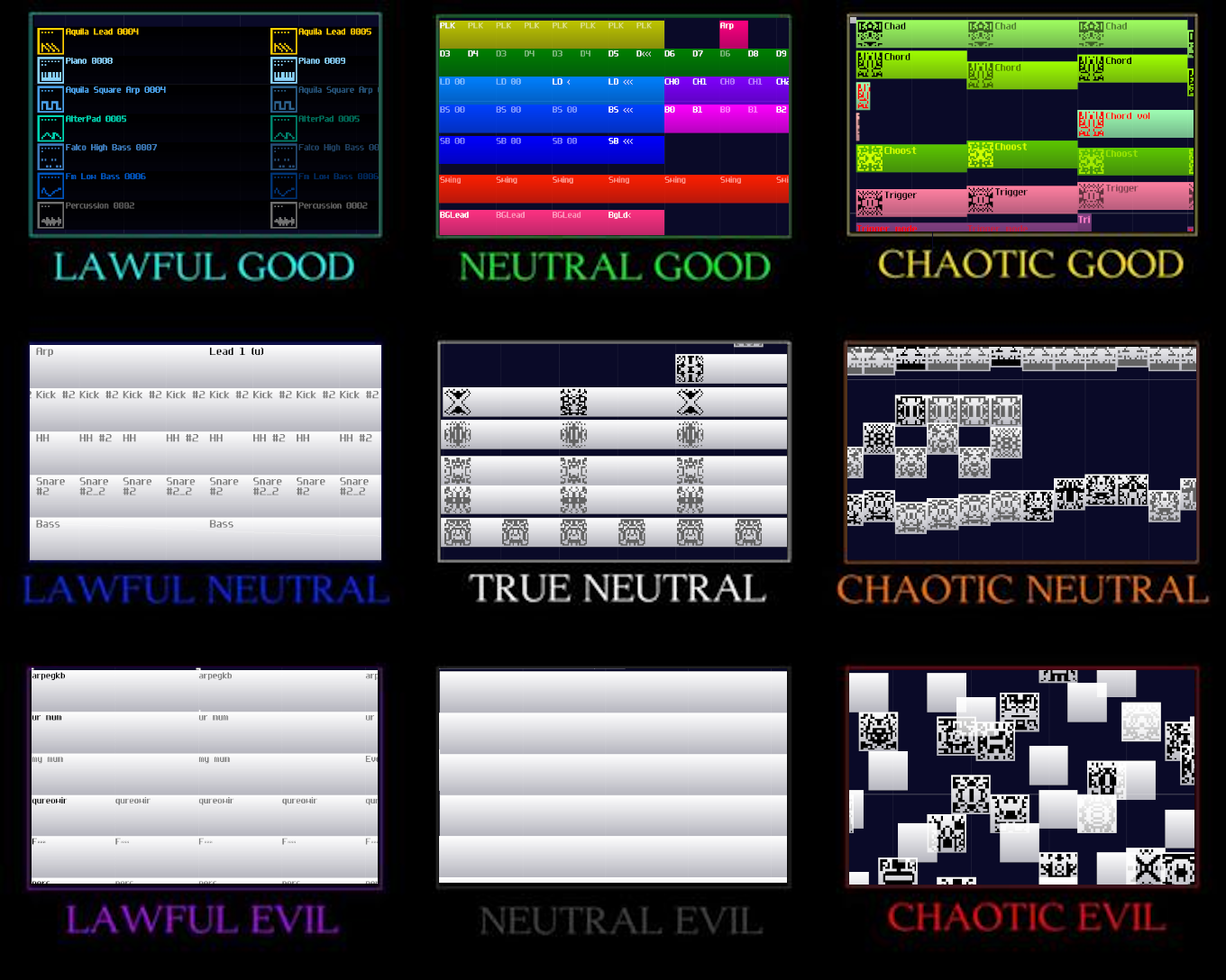
Of course, you can build your logic thingies without noties organizing or planning, and in fact, I did this once with my pong module.
This module is really messy, and overlapped modules and connections are everywhere; as a result, I couldn't able make any update with this module. Hence, like writing your normal python or c program, "Coding Practice" is also existed in SunVox if you consider it is a visual programming language just like Reaktor or Pure Data.
Module Flow Direction
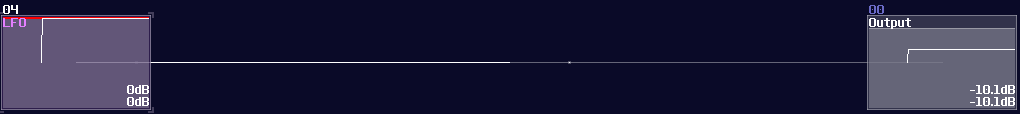
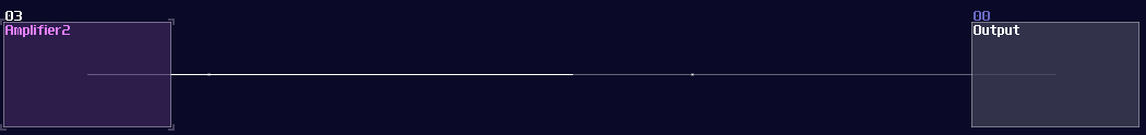
Unlike Rick and Morty, you don't need a high IQ to understand the module direction in SunVox although it looks subtle. You can see the brightness of the line, which the brighter side is the sender, while the darker side is the receiver.
It is important to remember this little detail because it is really tedious and boring to point out every single routing details of circuits while you don't need to implement most of them (all you need to do is to use my pre-made logic processing modules). I have tried that once, but drawing arrows doesn't seems to work if the contraptions are complex and tightly packed.
Special Symbols in Modules
Besides coloring which I will talk about for the later chapters, labels are also important to tell the functionality of modules. This is not only used in logic processing, but also in module design so that assigning controllers would become easier.
Here are some of the most frequently used prepended labels for my module design:
| Symbol | Meaning |
|---|---|
| >> | Midi and Audio Input |
| ## | Controller Input |
| -- | Wire |
| == | Bus |
| [id]' | Sender (from) |
| '[id] | Receiver (to) |
| ] | Modules are not connected to the left until [ |
And some appended lables:
| Symbol | Meaning |
|---|---|
| [ | Modules are not connected to the right until ] |
| /\ | Modules are not connected to the top until \/ |
| \/ | Modules are not connected to the bottom until /\ |
Some of the labels are function specific, and I will tell you about those in the following chapters.
Overlapping
This is the root of evil of an unreadable project, overlapping makes the flow of module hard if not untraceable. There are two types of overlapping:
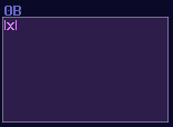
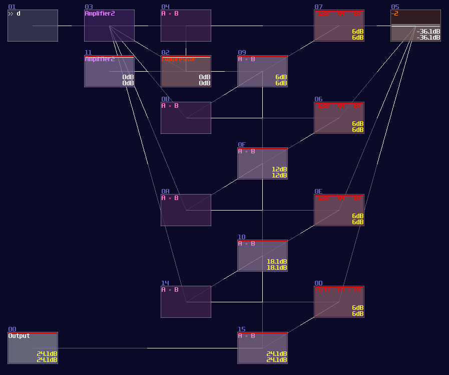
The first one is overlapped modules, which must be avoid since this not only hides all the connections, but also it has no way to tell what it does! Can you tell what is the output to this "module"?
No one will get this correct because it was the 2's complement implementation while every module were squeezed into a singularity.
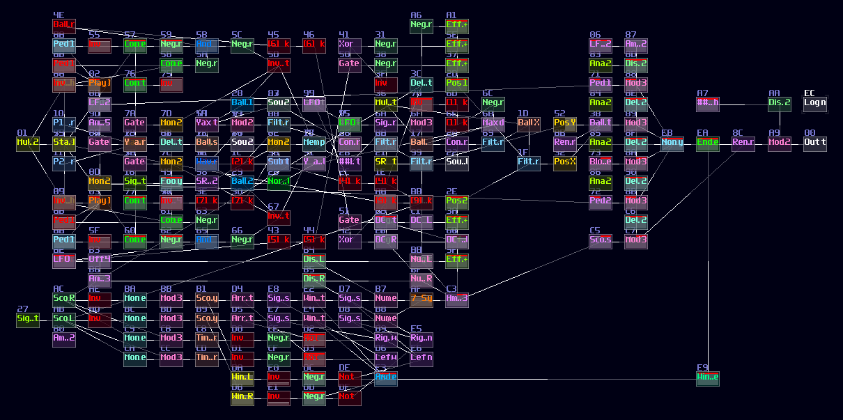
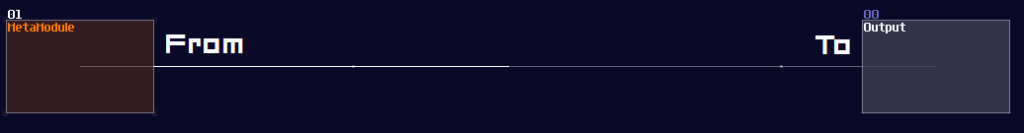
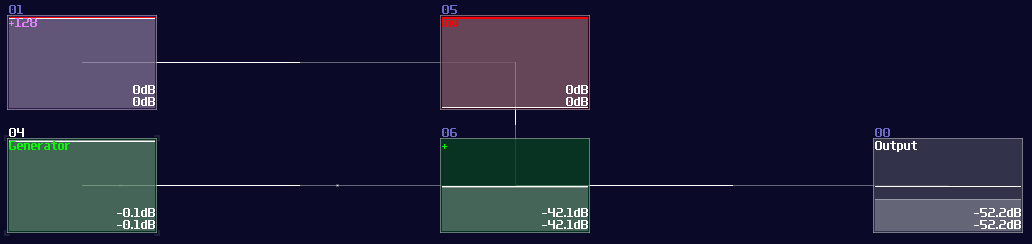
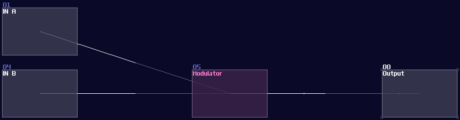
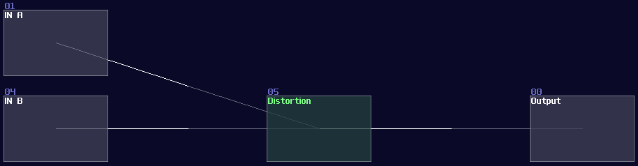
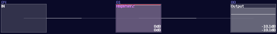
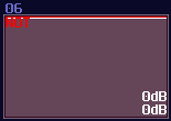
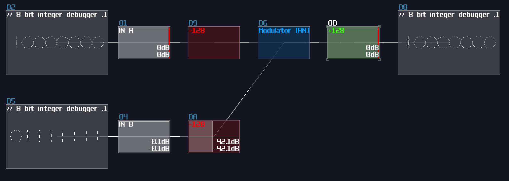
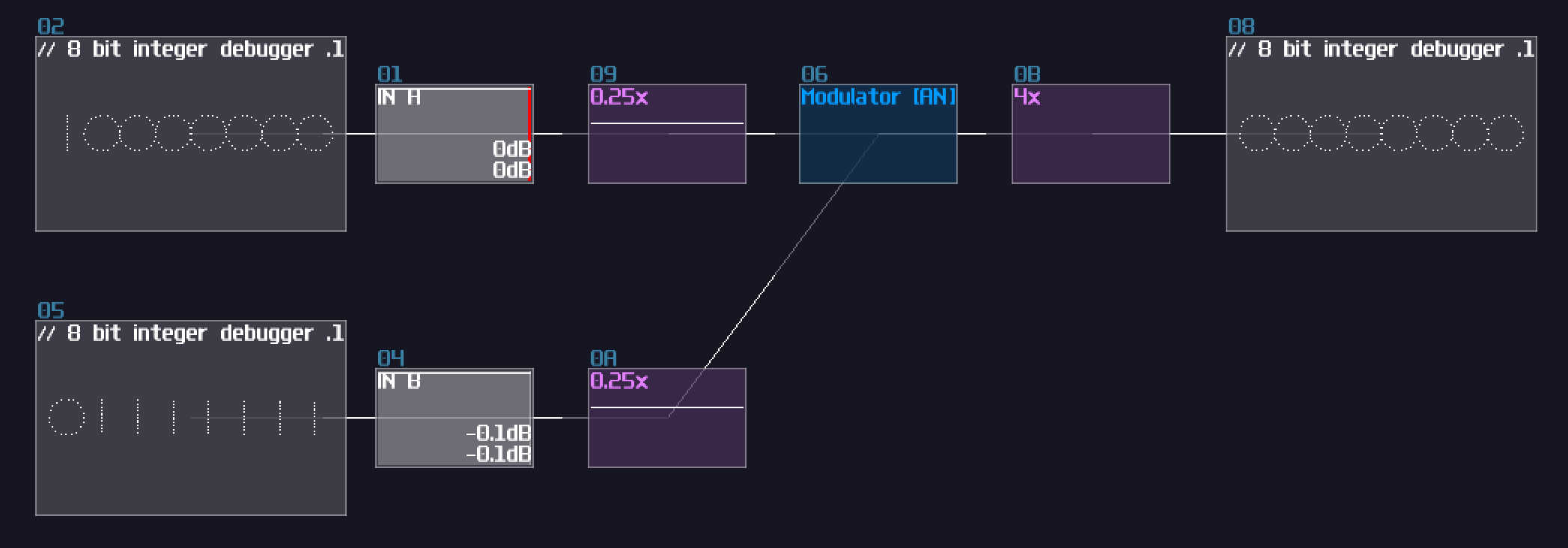
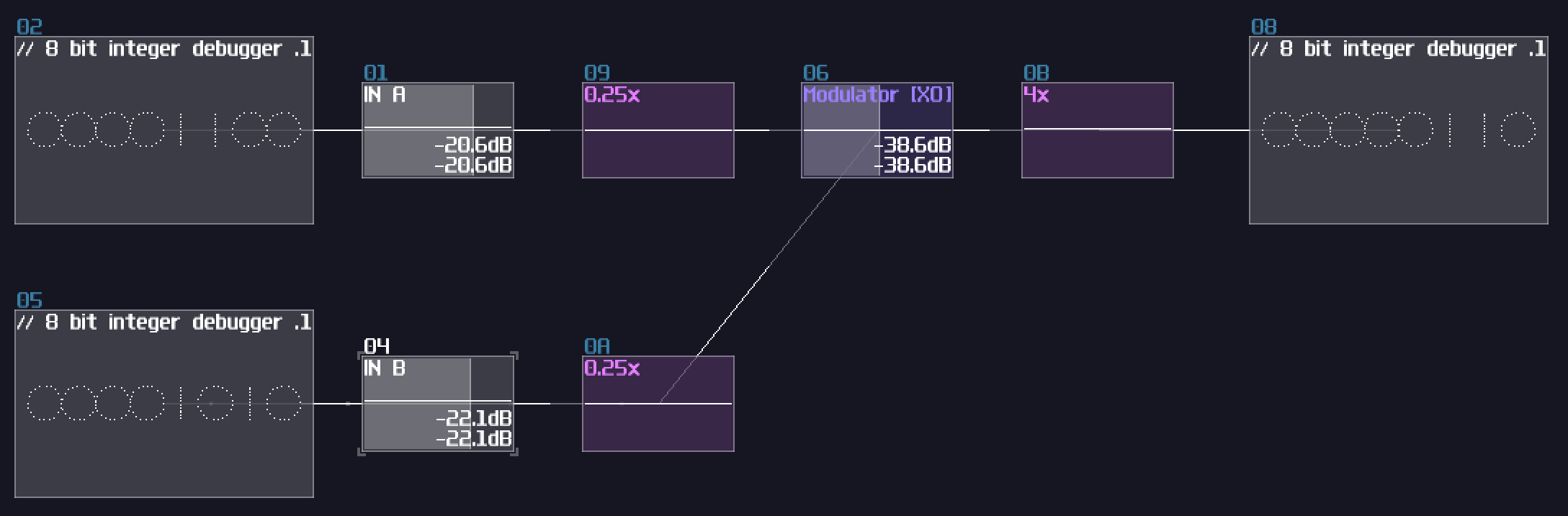
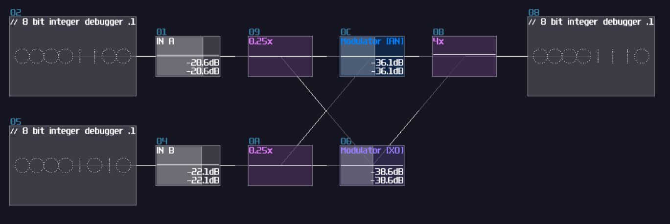
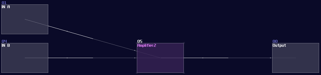
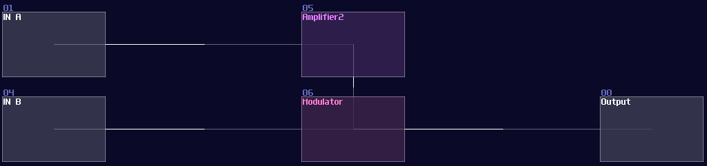
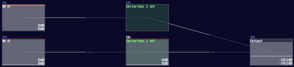
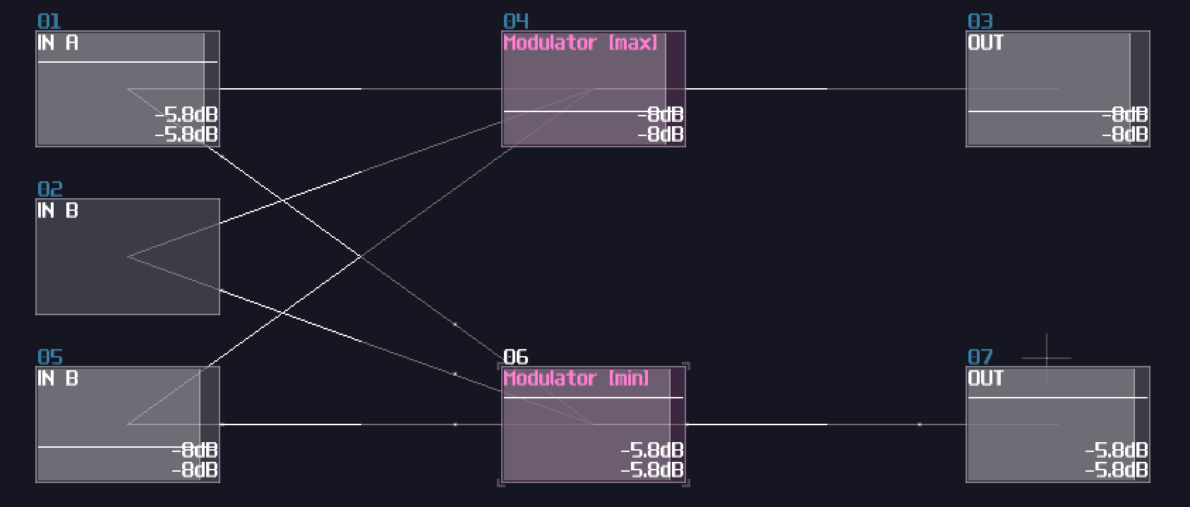
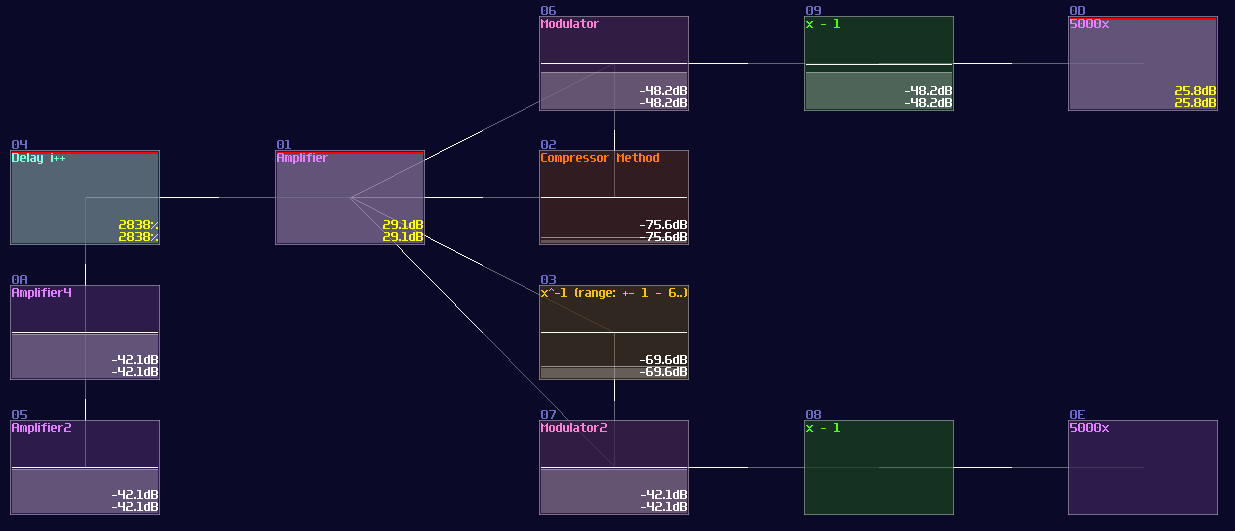
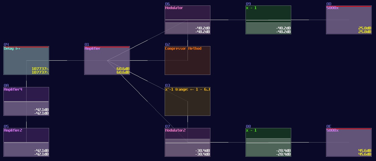
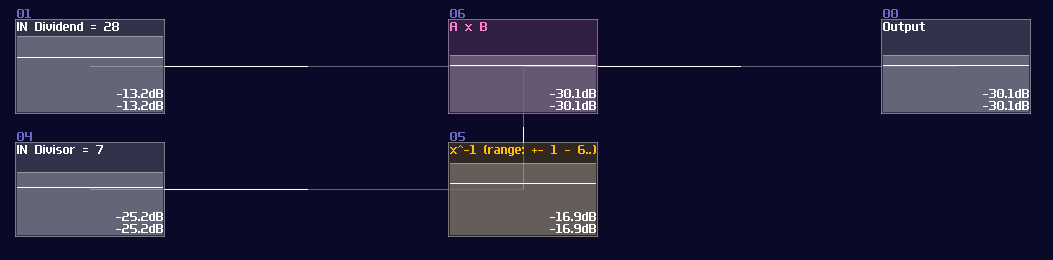
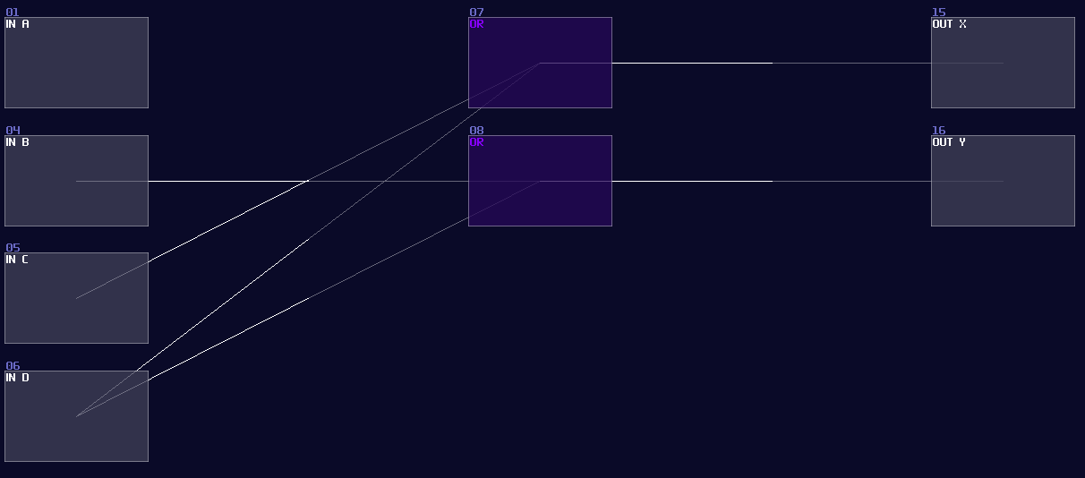
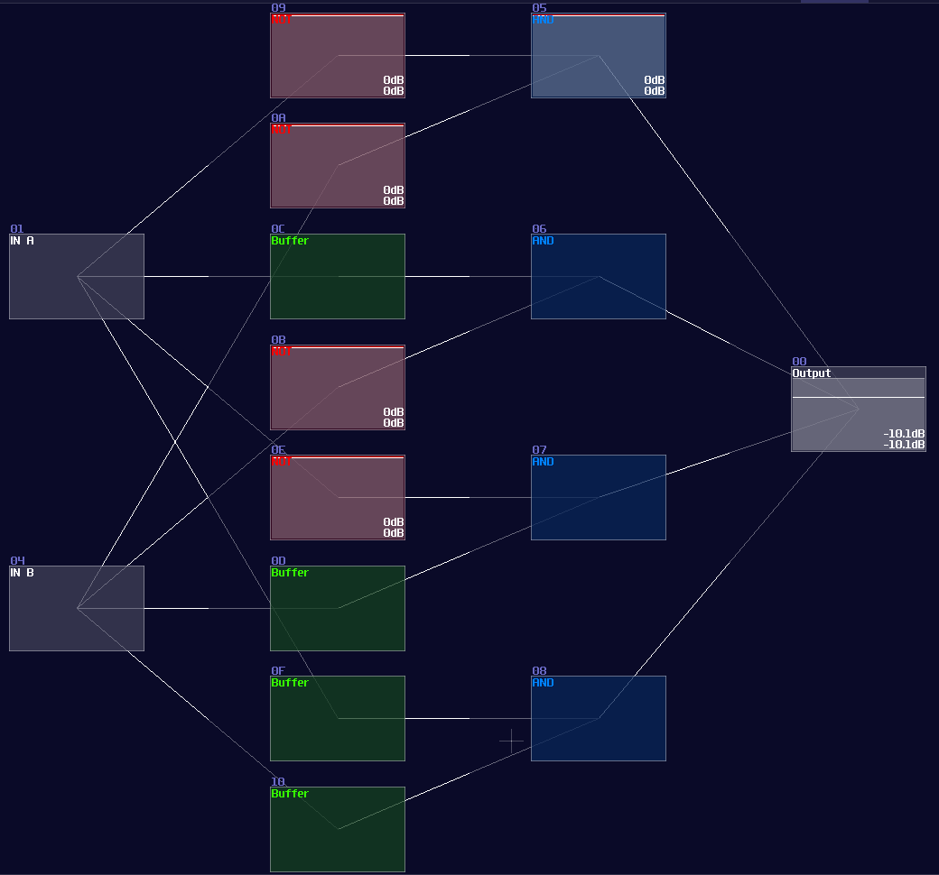
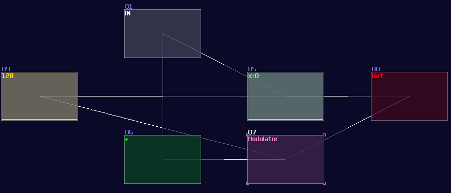
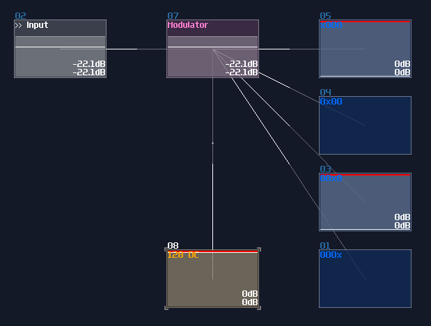
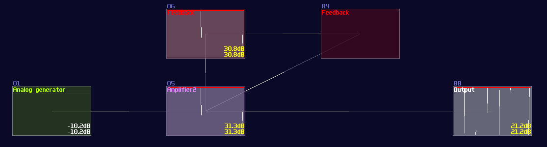
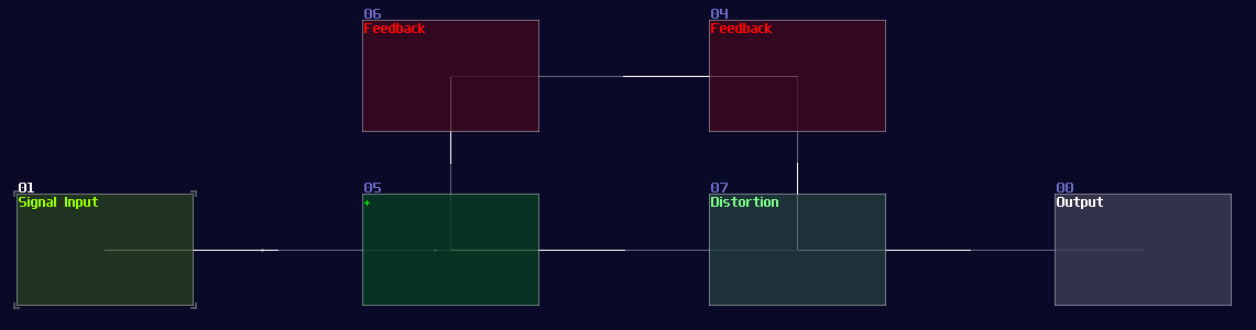
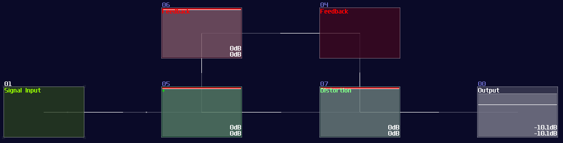
Another type of overlapping is rather common, the overlapped connections; let's look at the following image, and let's see if you can tell the difference:
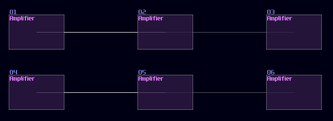
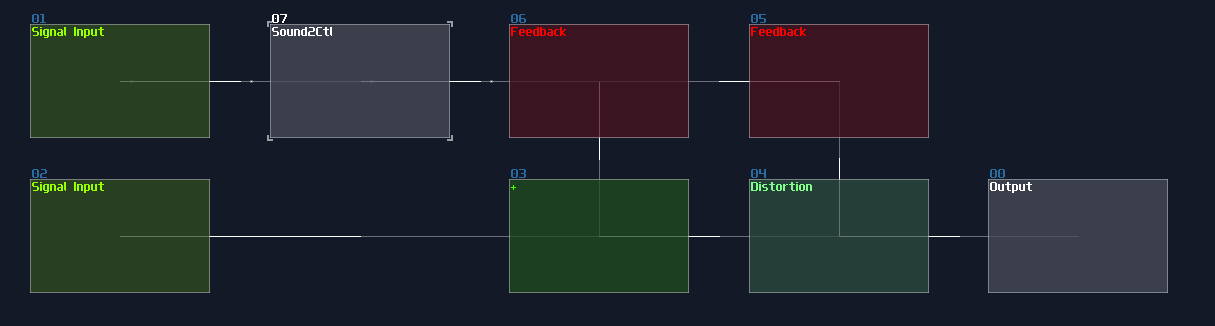
The answer is... Module 01 connects to module 02 and 03, while Module 04 only connects to module 06, and the module 05 doesn't connected with anything! This leads to a great confusion because there is no way to tell if there are any hidden links under the original link; nevertheless, you might be forced to stack your links to achieve a more readable, compact design in term of the module organization, and you may use some of the prepend or append labels, acting as hints.
This is not desirable, but at least there is some hint to tell how the module are connected.
Input and clock
Overview
Before talking about any components and logic, let me tell you about how to make some inputs in order to test your logic stuff.
There are two type of source modules that you often use:
1. Pulse
The most basic type of input source, all you need to do is to use a generator with drawing a waveform in a constant DC: Generator Drawn Mode:
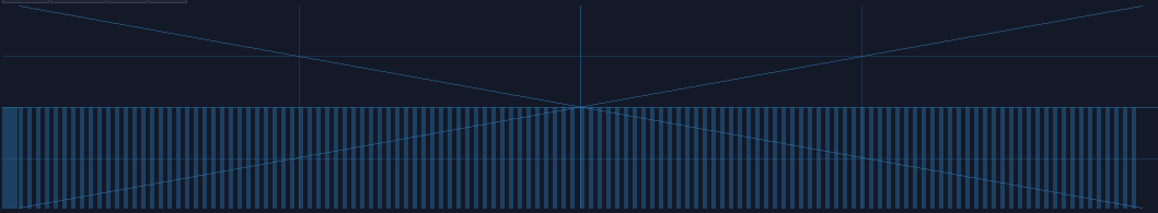
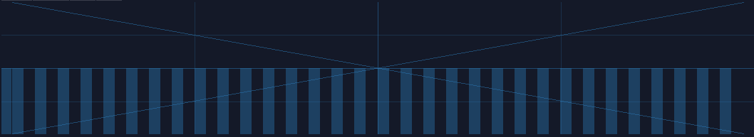
However, this is not the best solution, since this is not a perfect DC signal, which it has a slight offset to the ideal +128 DC offset in the amplifier. To prove the issue, we can perform a null test, using an ideal signal source as an control. Inverted that signal, and add the signal with our own signal. If the signal are perfect, they will be cancelled to each other.
In this case, we can subtract our DC signal with the amplifier signal:
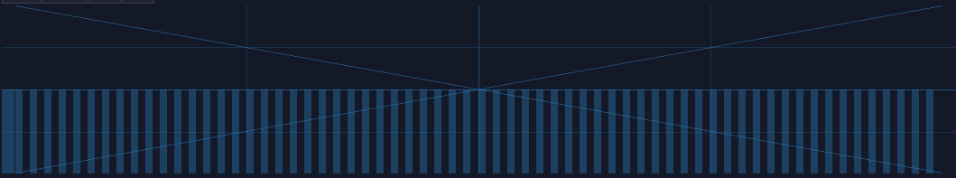
As expected, you can see a thin line after combining two signal, suggested that both of the signal are different in magnitude. To Fix the issue, we need to use a distortion, setting the bit depth to 2, while doubling the volume, to make a perfect +128 DC offset signal:
2. Clocks
In come cases, you need to send a periodic signal for your circuits, all you need to is to firing your generator in a precise timing. You need a clock to do such a job for you.
To build a basic clock, you only need a LFO module, with these particular settings:
| Controller | Values |
|---|---|
| Waveform | square |
| Generator | on |
| Smooth transitions | off |
That’s it, now you can change the frequency to make it go faster or slower, based you your needs to your logic structure.
The advance way to build sources
Logickin, You lied, you didn’t use these input source in your VOXCOM 1610! Well, that is why I am now showing you a more advance way to build pulse or clock generators. The following implementation is a bit more complicated, but it offers a cleaner signal for projects that require higher timing precision.
At first, create a metamodule:
Click the edit button of the metamodule, and add an amplifier inside the metamodule like shown
Once you have that amplifier, create a pattern with a length of two. Then set the automation as the following which it changes the DC signal of the module:

Exit the metamodule, and set the playback of your metamodule to on (repeat) for clock signal, or on (no repeat) for pulse signal.
Here we go, there are the commonly use input source for testing and powering your project, now we can move on to build your first set logic gates.
Example Project:
Logic Gates
Overview
Fundamentally, every computers are made with some kind of logic gates, which is the simplest component to calculates things. In the real world, logic gates are made with a bunch of transistors. In layman terms, transistor is like a switch (there are more than that, but let's keeping it simple). When you press the switch, the light is on, and vice versa. Instead of flicking the switch manually, electronics switch on transistors using voltages.
Binary and Truth Table
Without mentioning what is a Binary and Truth Table, it is meaningless to teach the following since they are the vital concept and figures to show how logic gates work.
Computers don't calculates math like us, using the decimal number system; under the hood, they are just all low state or high state; some call it 0s or 1s; some call it true or false, and they all describe the same thing, the binary signal. For now, let we use 0 for no DC signal, while 1 for DC signal with +128 DC offset in amplifiers.
In Digital Logic, we also have an useful diagram, called the truth table, to show how a logical component behavies under certain inputs. For example:
| IN A | IN B | OUT |
|---|---|---|
| 0 | 0 | 0 |
| 0 | 1 | 0 |
| 1 | 0 | 0 |
| 1 | 1 | 1 |
This table shows how AND gate works by flicking the input one by one, with all of the combinations, so this clearly tells the AND gate only switches on when both input is on.
That's about the truth table, let's talk the logic gates.
AND Gate
The first one is an AND gate. You must switch on both of the input to set the output on, the following is the truth table and the simulation of the AND gate.
Truth table:
| IN A | IN B | OUT |
|---|---|---|
| 0 | 0 | 0 |
| 0 | 1 | 0 |
| 1 | 0 | 0 |
| 1 | 1 | 1 |
Simulation:
To build an AND gate in SunVox, all you needed is a modulator and... that's it, since you can consider AND operation is like a multiplication. If either one of your input has a Zero, the product must be resulted in Zero; otherwise, you will get an one if both of your input are one.
Despite being a single module, I tend to change the color to blue and name it AND/Transistor to reflect the purpose of the module. There is a difference between two, AND is when both of the input are binary (0/+128), while Transistor can have one of the input in any magnitude just like how real life amplifier increase the gain of a incoming analog signal by changing the gate voltage.

OR Gate
The second commonly used logic gate is OR gate. The output is on as long as you have switched on at least one input. It seems that OR gate is quite useless at first glance, since you can set the output to 1 if any one of them are 1, but it is useful for making multiplexer or grouping control signal. Here is the table and the simulation:
Truth table:
| IN A | IN B | OUT |
|---|---|---|
| 0 | 0 | 0 |
| 0 | 1 | 1 |
| 1 | 0 | 1 |
| 1 | 1 | 1 |
Simulation:
Building an OR gate is as simple as an AND gate, but you need a distortion instead, and setting the distortion as shown:
| Controller | Values |
|---|---|
| Volume | 256 |
| Bit depth | 2 |
Once you have done right, the distortion will always regulate the signal into constant +128 DC, if you switch on at least one of the input. Normally, I prefer to change the color of the OR gate into purple:
NOT Gate
The third of the trine is a NOT gate, also known as an inverter. Unlike AND or OR gate, it only has one input. It is useful to create common structure like decoders, conditional checking, or simply to invert the output signal.
Truth table:
| IN A | OUT |
|---|---|
| 0 | 1 |
| 1 | 0 |
Simulation:
Building an inverter is also easy, you only need a single amplifier.
Despite having such a simple structure, there are two variants in NOT gates; depends on the type of application, you may set your amplifier into one of the configurations:
The first type is a non-inverted NOT gate, where the input signal is a +128 DC offset:
| Controller | Values |
|---|---|
| DC Offset | -128 |
| Absolute | ON |
Another type of inverted NOT gate, where it takes negative 128 DC offset as input, which is commonly used in zero detection.
| Controller | Values |
|---|---|
| DC Offset | +128 |
| Absolute | ON |
I generally prefer NOT gates in red color.
NAND and NOR Gate
Despite not common in SunVox, Nand and Nor gate are worth a mention. They are known as universal gates, meaning that their properties can emulate all other logic gates. Universal gates are common in real world digital circuits, due to its properties able to simplify the design. To make such gate, all you need is to attach a not gate after the output of the AND/OR Gate. Nonetheless, they required one more module to implement, so they are not frequently used in SunVox.
Truth table and simulation of a NOR gate:
| IN A | IN B | OUT |
|---|---|---|
| 0 | 0 | 1 |
| 0 | 1 | 0 |
| 1 | 0 | 0 |
| 1 | 1 | 0 |
And a NAND gate:
| IN A | IN B | OUT |
|---|---|---|
| 0 | 0 | 1 |
| 0 | 1 | 1 |
| 1 | 0 | 1 |
| 1 | 1 | 0 |
As you can see, you can emulate any logic gate using NOR Gate only, due to its property of being a universal gate:
XOR and XNOR Gate
I used to planned to build a XOR gate as my first question as my SunVox Logic Riddle, because it is a bit complicated compared to all other gates. How XOR gates works is similar to OR gates which the output stay on if one of the input is on; however, when both of the output is on, the output is off:
Truth Table:
| IN A | IN B | OUT |
|---|---|---|
| 0 | 0 | 0 |
| 0 | 1 | 1 |
| 1 | 0 | 1 |
| 1 | 1 | 0 |
Simulation:
Likewise, there is an Inverted version as well, which is a XNOR gate. The output is the opposite to the XOR gate.
I thought XOR gate was difficult to achieve because you may need multiple modules to make one, and I was planning for using this as the first question for my riddle; however, there is a much simpler solution which is based on a non-inverted NOT gate. Based on the NOT gate setting, we can find that the equation of that gate is the following:
\( y = |x - 128| \)
Since the signal strength of a true signal has been defined as +128, we can cancel out the offset by a single input, causing the NOT gate to switch off. If we feed 2 true signal into a NOT gate, the calculation will be 128*2 - 128. The offset of +128 will set the gate as true state again, making it behaving like a two input XNOR gate. To convert it into an XOR gate, only an extra NOT gate is required, appended at the "NOT" gate that acts like an XNOR gate.
DeMorgan’s Theorem
"There are way too many gates now, how can I remember them all?" Seems there are quite a few of logic gate to remember, but if you look closely, you can see there are some commonalities to one another, which is the use of NOT gate at the input and output. In fact, we can convert most of the logic gate into another, by wrapping NOT gate at the I/Os, known as DeMorgan’s Theorem.
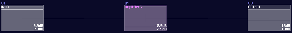
Take and AND gate as an example; if you invert all the inputs and output, you will get an OR gate as shown:
Likewise, it also applies to other gates.
Conclusion
That's it, this is all of the common logic gate and its implementation in SunVox. I will attach a SunVox project to demonstrate how these gates works and what is the setting of these gates:
Example Project:
Logic Gates Extended - Bitwise Operation
This is the extension of the previous chapter and they might contains advance concepts; if you feel overwhelmed, please move on to other chapters first and goes back to this chapter once you are ready.
Overview
Thanks to the 2.1.2 update, bitwise operations are now possible which it opens up a whole new dimension of possibilities. Let we explore about the latest features, to build logic gates that can process information in parallel.
There Are N Binaries Among Us
Before know how to stack logic gates within a single module, we need to understand what is a binary (or base 2) number:
Binary only have one and zero for every digits, so instead of the traditional base 10 which it has 10 times more value than their previous digit, binary only doubles its values. Because each digit now has either on or off state, we can perform basic logic with each digit separately, thus a bitwise operation.
Bitwise AND
Thanks to the "bitwise and" mode in the modulator, we can squarely feed two source into the modulator for such operation:
As you can see, the bottom input masks out the input above, only showing the digits when they both true. This is useful when computer memory is limited because you could use that to store 8 separate indicators within a byte, and parse them using the AND operation. In SunVox, you could reduce the number of modules by 87.5% ** using this method compared to process the bit one by one. (if you build a bitwise operation processing a byte)
There is a catch though: Since the modulator in bitwise mode only works up to ±127 DC unit, we must ensure the input never goes beyond the limit; nevertheless, you can't simply extend the bit width by subtracting input and normalize the output by 128 DC unit because there is an edge case when both of the input is +128 and +127 DC unit respectively, ending with a wrong result:
To solve this issue, we need to do a simple trick. The reason I have chosen DC unit to represents bits purely because DC offset controller in amplifiers are easy to work with, while it is easier to have a consistent result; in fact, the bitwise mode in modulators can go finer than that, and you can declare your own bit step size by dividing and multiple by N before and after the modulator respectively:
With this design, because I have divided and multiplied the gain by 4, forcing the modulator perform bitwise operation in a finer resolution, I have extended the operation by 4 bits, without crossing 0 that trigger the edge case.
** theoretical assumption and assume 1 bit is defined by 1 DC unit
Bitwise XOR
With the same principle, we can swap the modulator mode to bitwise xor:
Bitwise OR
Beyond AND and XOR, it is possible to construct other bitwise operations, but we need to find the logical expression. Since we know that OR operation means at least one of the input is true; meanwhile, AND is true if both of the input is true, while XOR is true only if one of the input is true. Because of that, we can combine both of the signal to form a bitwise OR operation:
Bitwise NOT
XOR gate is a versatile logic gate in SunVox; instead of feeding two individual input, all we need is to feed one of the inputs with a constant that represents all true (usually \(2^x - 1\) ):
Conclusion
With all these new features delivered in 2.1.2, we can now perform bitwise operations to manipulate individual bits of a number; in addition, we are one step closer to build the quake 3 inverse square root!
Example Project:
Numerical Operations – Basics
Overview
Since computers are worked in binary, it make sense to build a computer with such mindset. Normally, If I ask people how to add two 8bit numbers logically, people may said to build a full adder; however, since SunVox is a highly consistent and noise free environment, you can represent a data more than just binaries.
Let’s take a look in Amplifier, you know that you can find a DC offset option. If you move around the control, you can get a constant DC signal. That is the key of this chapter, since DC offset in amplifier has 257 steps, which is enough for representing a 8 bit integer. Hence, We can make use of this feature, to simplify some commonly used structure like adders and decoders.
Here are some of the the most basic mathematics and checking operation you would use in SunVox logic processing. They might sound like a joke at first, but you will find that most of the magic are just the following logic. There are more advance tricks as well, but this chapter will only go through the basics first.
Addition
Addition is common in SunVox because mixing two audio signal is already an addition; thus, we may use an amplifier (or modulator in add mode, or EQ) with default settings to combine two values.
There might be other features for additions as well, and will talk about that in the later sections.
Subtraction
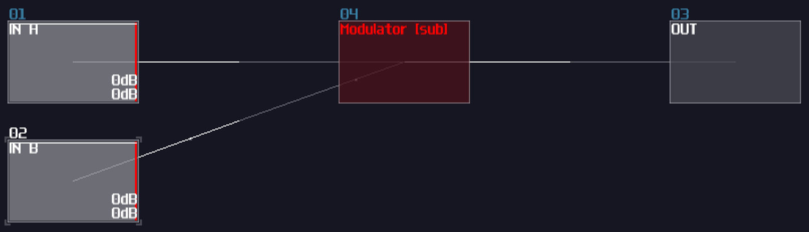
"How about subtraction?" People may ask. For the beginner level, we can simply using an amplifier to invert the signal by seting the Inverse controller to on. Since you have negated the original signal, you can minus any number by combining the negated number as shown:
Alternatively, since the 2.1.2 update, we can also use the subtraction mode in modulators:
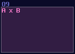
Multiplication
There are two type of multiplications, the first one is static multiplication which you only need to change the gain of an amplifier to do the trick, which is not special, so I am not going to show any image about that.
Moreover, most of the equations don't just multiply over a constant only, so that is the reason why we need dynamic multiplication. To multiply any number, you need to multiply one of the input with a gain of 128, normalizing the signal ; thus, you will something like shown:
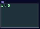
Negative Detection
Distortion has an interesting property when you set the bit depth to 1: If the value is less then 0, distortion generates a constant negative 128 DC signal; otherwise, distortion will not give any signal. This property is useful, as this gives SunVox an efficient way to do conditions.
Min / Max
If you want to find out the highest and lowest values given the input signal paths, modulators can accomplish the task with using "min", "max", "min abs" and "max abs". They pick up the highest/weakest signal out of all signal paths, while the abs mode only consider the magnitude of the signal.
Naming and Coloring Conventions:
Unlike logic gates, coloring in numerical operations are not defined by the module type, but the equation type, and there are a few catergories:
If the function is Amplifier based while it only process positive number, I normally set them to green:
When there is an inversion or subtraction, I would set it to red, since they all have the idea of opposing and negation from the inputs:

If the module only process absolute, the color will be retained as the original color of amplifier:
So do multiplication and negative detection:
These are not strict rules; as long as your coloring is consistent, it is not necessarily to follow the coloring.
Conclusion
Here we go, here are the basic numerical logic in SunVox, but you may wondering: how about division; how about geometries; how about squareroots? No worries, I will tell you about that later since they are more complicated.
Example Project:
Numerical Operations – Dynamic Division
This is the extension of the previous chapter and they might contains advance concepts; if you feel overwhelmed, please move on to other chapters first and goes back to this chapter once you are ready.
Overview
Due to the re-discovery of the properties in waveshaper lookup tables, quite a few mathematical operations, considered as impossible, have been brought into the reality. Let we show you the first problem:
Division has been my headache since I was messing around logic stuff in SunVox, as most of the division methods require a dynamic number of iterations. This is not really an issue in computers because they have ultra high clock speed and low feedback latency, making the process time being unnoticeable; nevertheless, this is not applied in SunVox owing to its rather long 20ms feedback delay and its limited sample frequencies (44100, 48000 or 96000 in most cases). As a result, division will take ages to complete.
Take 8455 / 2 as an example; if we loop for every iterations, we ended up increasing an accumulator by 4228 times, which it takes (4228 * 20) / 1000 = 84.56s. Roughly a minute to complete a single division is horrific because not only we ended up with wasting all the time to do a simple task, but also making the machine hard to predict the run time. Thus, we must find something better.
Basic Long Division
Let’s look at the first non-iterative method. Considering that we only need to divide a single bit, we only need to know a few things:
- Is dividend (Numerator) large enough for cancelling the divisor (denominator)?
- If so, how to represent the answer?
- How to handle for the remaining values?
As you can see, since we need to compare number between dividend and divisor, negative detector is needed, and because negative detectors only switch on when dividend is smaller than the divisor, we must apply an NOT gate for the answer. We must sort out the remainder as well, so we must return the subtracted result during comparing the the two inputs; hence, we have the following:
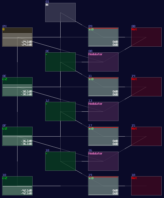
But... why is this have a x2 for the divisor side? This is the middle stage of the division logic, which the divisor is multiplied by two for each stage, except for the first stage. Thus, the divisor is grown exponentially by passing every stage, to minimize the number of subtraction by representing the answer in binary form. If we apply this rule, by chaining 8 of them, we can get a 8 bit division circuit:
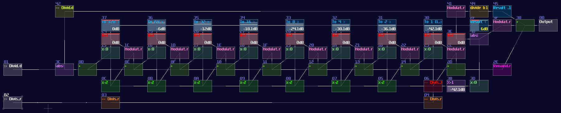
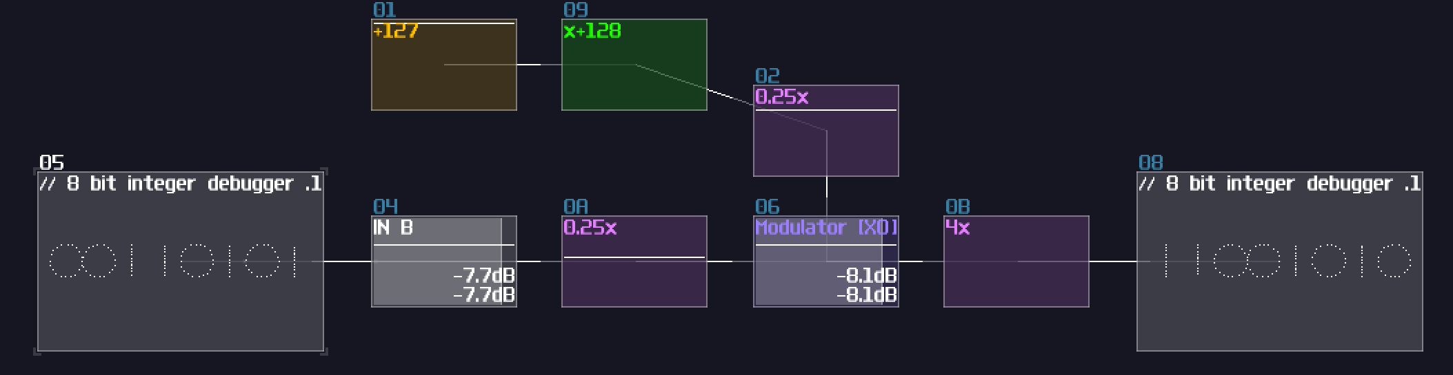
It works because it is basically a binary long division; if you insert 67 / 5 into the structure, it triggers stage of 8x and 4x and 1x which is 13, while the remainder 2 is shown in the remainder module. (Module 2E in the image of 8 bit division structure). It works on decimal number too since there is no quantization, so you can easily fill a equation of 10.6 / 5.3 and you can still get a two.
However, this circuit has two flaws. The first problem is quite obvious that the result does not support answers with decimal point, so you cannot compute anything precise; another problem is the range of operation is narrow. Even though you can extend the number of stages to handles larger number or finer fractions, it is unrealistic that the division circuit is so huge which might consumes too much CPU power, so this implementation is not ideal yet.
Newton’s Method With Waveshaper
You might already know in the “Waveshaper In LQ Mode Redifines SunVox Programming” post. Let me tell about about the Newton’s method which includes a division algorithm which provides a great result with a small, fixed number of iteration. All you need to know is the following equation:
\[ x_{n+1} = x_n ( 2 – a x ) \]
a is the number you want to invert while x is the initial estimation.
To find the best initial estimation, the initial estimation must not exceed 1.5 times of the actual result. With a great estimation, you can get a great result of 1/x. In this example, we find the result of 1/16.56 with the estimation 1/16, which provides a result that is accurate after 15 decimal points:
\( x_{n+1} = 0.0625 ( 2 – 16.56 \times 0.0625 ) = 0.0603125 \) \( x_{n+2} = 0.0603125 ( 2 – 16.56 \times 0.0603125 ) = 0.0603863828125 \) \( x_{n+3} = 0.0603863828125 ( 2 – 16.56 \times 0.0603863828125 ) = 0.0603864734298157 \) \( x_{n+4} = 0.0603864734298157 ( 2 – 16.56 \times 0.0603864734298157 ) = 0.0603864734299517 \)
On the other hand, you can’t estimate a number from 0.5, if the number you want to invert is 5 which the correct result should be 0.2 because 0.5 is 2.5 times greater than 0.2. In consequence, you will go to infinity and soar beyond the ideal range:
\( x_{n+1} = 0.5 ( 2 – 5 \times 0.5 ) = -0.25 \) \( x_{n+1} = 0.25 ( 2 – 5 \times 0.25 ) = -0.8125 \) \( x_{n+1} = 0.8125 ( 2 – 5 \times 0.8125 ) = -4.92578 \) \( x_{n+1} = -4.92578 ( 2 – 5 \times -4.92578 ) = -131.168 \)
That is the reason why we need a lookup table from waveshapers. To get the optimal lookup, we may follow the following equation:
\[ f(n) = \begin{cases} 0.75, & \text{if x = 1} \\ 1/x, & \text{otherwise} \end{cases} \]
The reason for the 0.75 when x = 1 is to avoid the >1.5 problem when x is between 1.5 and 2. Because we already have a lookup table of 1/x, we can not only have a relatively good initial estimation, but we also can do 8bit integer division out of the box. (except for 1)
Now we can apply the Newton’s method as shown:
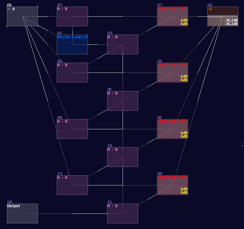
You may see there are four stages of duplication, and they are exactly the equation of \(x ( 2 – ax )\), which the upper modulator represents \(ax\) while the lower one represents \(x (…)\), and the red modules represents the result from \(2 – ax\).
After \(x_1\) has been calculated, it is passed to the modulators of the second level, to do the second iteration, and so on, and we extract the result at the last stage.
This design has a limited range, but its audio rate performance is perfect for sound design like physical modeling and filter design, you may conditionally prepend and append a module for multiplying input and output over a constant to get a wider range.
Newton’s Method With Compressor
Right after I have posted the division module, fuzion_mixer asked a question:
I don’t know if you have thought about trying to do division like this: Controlling the Fine Volume in 04 alters the value in the compressor in which a curve that looks like 1/n. The only problem is that it has a lower threshold of 128 before it starts curving.
Along With the old post about a compressor design issue, which NightRadio had posted the fixed version of the compressor algorithm; the algorithm basically only has a single division with a bit of other variables:
\[ Gain = Threshold / ( Threshold + ( Envelope – Threshold ) \times Slope ) \]
That is an interesting question because if we can use compressor instead, we can further simplify the design of the division module.
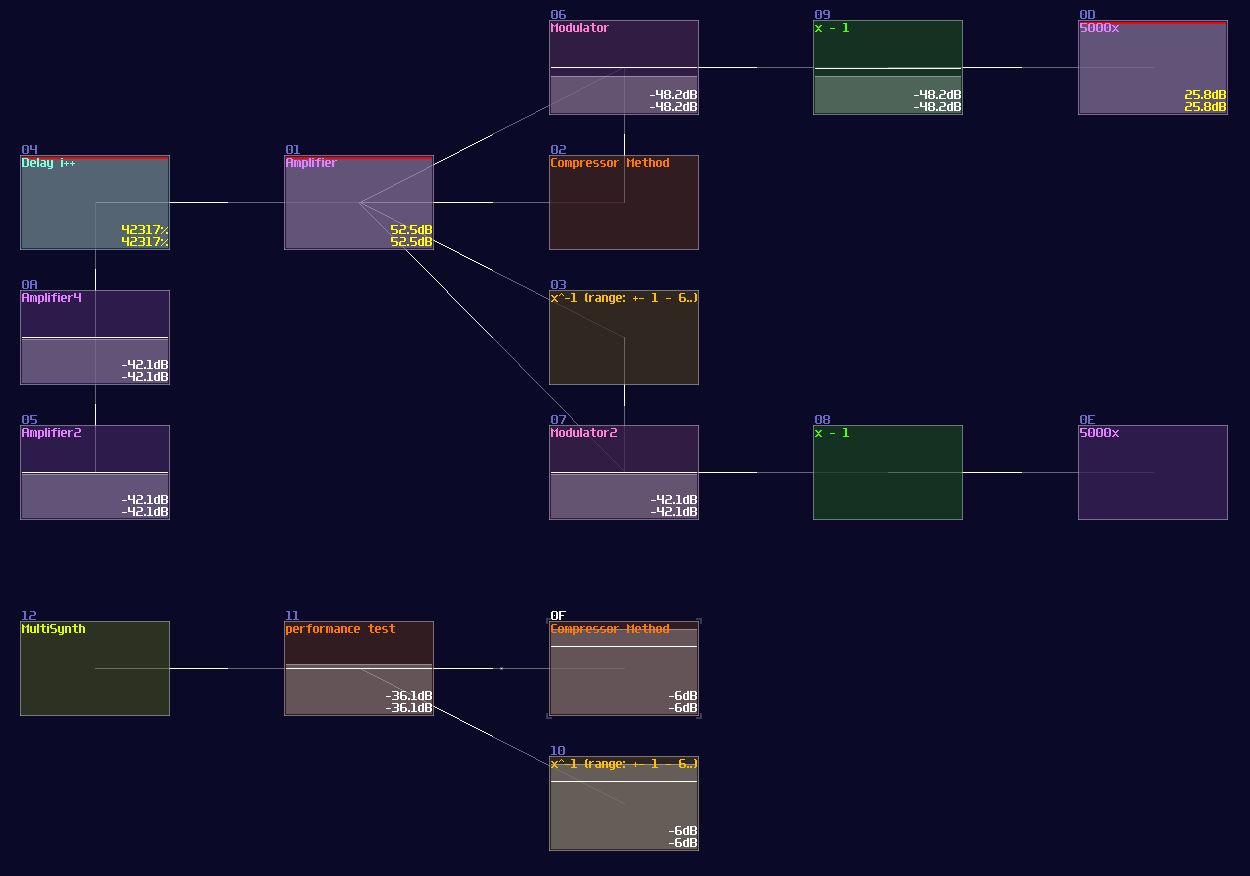
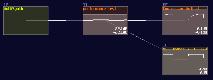
Thus, we did a test by using a compressor only; here is the original SunVox Project from fuzion_mixer, related to the compressor divider prototype, with a little re-coloring for explanation:
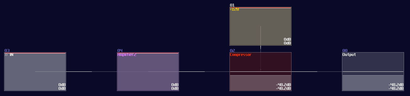
To test the accuracy, we made another project and performed a simple calculation, \( x / x \) . Since \( x / x \) must equals to 1, we can subtract another one after the division and multiply the subtracted result to see how large the error with both of the methods. Meanwhile, we also did a performance test by firing a fast pulse to see the respond time, considering the release time of the compressor might slow down the throughput:
With this approach, we have found a few properties with the compressor method:
For smaller values, where x < 65535, compressor has a slight worse precision than waveshaper, considering the little error after attempting to nullify the result with -1.
Eventually, due to running out of lookup and pre-multiplication, the waveshaper method losses accuracy, while compressor maintains the same level of error, making it great for application with larger range.
Nevertheless, because the release can not be zero, the compressor introduces a little latency, so that is not ideal for realtime application:
This is a great discovery since we have more than one way to divide a number with less CPU usage, so we decided to replace the waveshaper with a compressor for initial estimation in order to provide a higher precision.
Although it has more modules than the purely compressor method, it still has lower CPU usage because of the lack of pre-multiplication (and fewer stage in the latest version), which this design is suitable for controlling signals in the Metamodule controllers.
Newton’s Method Inverter – How to
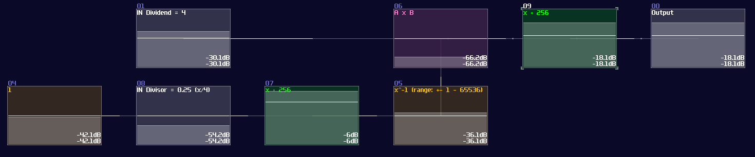
Instead of re-inventing the module, you may use my division module in my tool kit, including waveshaper and compressor inverter. As you can see from the example above, these modules only calculate the \( 1/x \) for the divisor instead of divisions. To divide a number, we need to do another multiplication:
To achieve number that is out of range for waveshaper inverter, we must multiply a value at the input and output. Take 4 / 0.25 as an example; this is out of range with the Inverter, so we must multiply the value before and after the inverter by a constant (256 for this example):
To make range extension more practical, you may also perform a range check when numbers have reach certain threshold by using subtraction and negative detection.
Example Projects:
Long Division Newton's Method Compressor vs Waveshaper Base Newton's Method
Numerical Operations - Square Root
This is the extension of the previous chapter and they might contains advance concepts; if you feel overwhelmed, please move on to other chapters first and goes back to this chapter once you are ready.
I have forgotten how did I mange to achieve this witchcraft, I need more information before I can complete this part of the tutorial
Overview
Likewise, without square root, most of the physics and geometries equation will be impossible. Finding length of a side from a right triangle, or calculate the projectile motions, you can't avoid square root. Because of the division module, this function has been finally brought into SunVox, so we can do a more complex math expression.
It was a difficult task because most of the efficient implementation for computers requires some form of hacking like using bitwise operation or overflowing the numbers which is impossible or inefficient to achieve in SunVox; hence, we had to seek other optimized solutions.
Square Root with Newton Method
Similar to the division, we can use Newton Method to find out the answer with the following equation:
Numerical Operations – Trigonometry
This is the extension of the previous chapter and they might contains advance concepts; if you feel overwhelmed, please move on to other chapters first and goes back to this chapter once you are ready.
Overview
Trigonometry functions are commonly used for splitting a vector into x and y directions, finding the length of a certain side of a triangle given an angle, or calculating or modeling any equations that have a oscillation. Similar to division, it also requires waveshaper to do the tricks.
Sine
Since Waveshaper can be used as a lookup table, we can build a trigonometric function easily. In fact, there is already a sine curve for waveshaper, ws sin2 curve in the curve folder. Thanks to the Symmetric Function in waveshaper; we can expend it to a full sine curve loaded in the waveshaper with DC blocker disabled (LQ mode is optional, depends on how accurate your application is.):
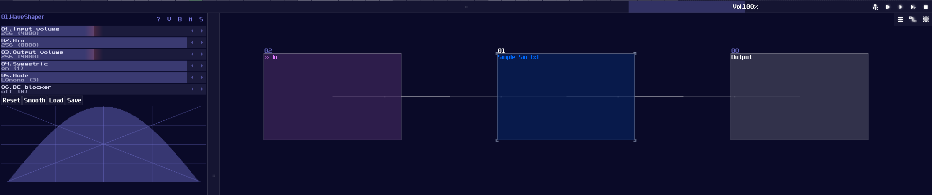
How this function work is when DC equals to 0 or 128, it corresponds to 0 degrees (0π), so the output is 0; when the input is 64, the degree and radian is corresponded to 90° and 0.5π respectively, so the output is 1, and so on.
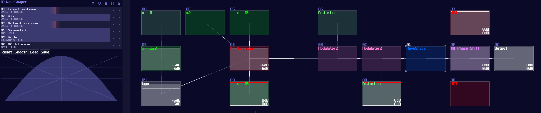
However, this is not a good solution because the peak of the sine function is not a perfect 1. To fix the problem, we must hard code the value one when the input is either 64 or -64 (±90° or ±0.5π), so to give out a perfect DC unit for these two specific case. Thus, with two extra number detectors to override the original imprecise reading; as a result, we have the following structure to find out a good approximation of a sine function:
Cosine
We can make cosine from sine by introducing a bit of offset, because you may consider that cosine is a phase shifted version sine. Hence, we can apply +64 DC offset which is same as adding 90°, to get the cosine waveform; nevertheless, the lookup table cannot wrap around if the input approaches to the limit, so we must add another set of detector, to check if the input value has goes beyond 64 so that to enable a signal to reset the lookup table.
Tangent
"So how about tangent?" people might ask. Tangent is a bit more complicated because it introduces infinity for every π/2, so it is impossible to get the perfect result when we close to the limit, but for the general case, it is possible for getting a reasonable approximation and we don't need to build another structure for that, thanks to the following equation:
\[ tan θ = sin θ / cos θ \]
Thus, we can use the divider to find out the value of tan like shown:
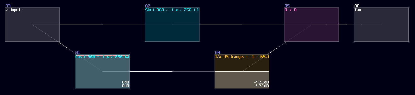
Since the division module have a limitation on representing infinity, the closer the input towards to π/2, the less accurate it becomes; hence, it method is only good for less precise applications like graphics.
Conclusion
That's about it, here are the commonly used Trigonometry function, and we have gone through the basic sin(), cos() and ten() using waveshapers. For now, let we pause the numerical operation for awhile and introduce some other basic components.
Example Project:
Delay Based Component
Overview
Besides logic gates and mathematical operations, there are delay based operations as well. Delay is another powerful module to let you not only delaying signal, but also limiting or expanding a pulse in a specific length.
Mono Stable Circuit
You might heard this term in some of the Minecraft Redstone videos. We also have them in SunVox too! Monostable circuits are used for converting a sustain signal into a pulse in constant time. It is useful for triggering Flip Flops and Latches (Introducing in the later chapters).
The simplest monostable circuits only contains a single delay module with the following settings:
| Controller | Values |
|---|---|
| Dry | 256 |
| Wet | 256 |
| Delay L/R | Timing in both channel must be same |
| Inverse | On |
At this point, if you feed constant DC input, you can see that the output stay lit for only the given delay time, and it switches if off itself afterwards, likewise if you release the DC input. This behavior is known as dual edge monostable because it only give of pulses with a limit of time at every switching point rather then the state. You may use a modulator to use the timing difference to eliminate pulses either at switch off or on, forming a Rising Edge or Falling Edge monostable circuit as shown:
Pulse Extender
Another well-known contraption in Minecraft; instead of shortening the pulse, we can extend it as well. To do this, we need a pulse extender. It is similar to making a monostable circuit, except to remove the dry signal and set inverse to off because no signal cancellation is required for this circuit.
| Controller | Values |
|---|---|
| Dry | 0 |
| Wet | 256 |
| Delay L/R | Timing in both channel must be same |
| Inverse | Off |
You must align the delay time with the period of your pulse. If the input pulse last 1ms, you must set your delay to 1ms. If you unsure about the time of your pulses, you may also make it shorter and more unified using a monostable to calibrate the length of your pulse before extend it. Once you have set the delay module, simply chaining a few delays in a row and sum all of the delayed signal and the input signal. With this configuration, you can extend the pulse n time by chaining n number of delay as shown:
Side Note: Due to 2.1.1 update, Modulator can also delay a signal with a maximum of 4 seconds, meaning that you can create structure above with dynamic delay time without using sound2ctl which is suitable for more precise and complex timing applications.
Conclusion
Here we go, now you know the two common uses for delay modules, besides simply delaying signal. You we see this module in the following chapters for more advance usages. For now, let we move on to the more complex stuff, some common combinational structures.
Example Project:
Encoder and Decoder
Overview
After you have warmed up a little by messing around the simple logic modules, let we move on to something more complex. Combinational Logic is a type of digital logic that only rely on the current input state, so this kind of structure don't remember any previous state, and calculate the result only using what the inputs have given. There are a few common combinational circuits, including:
- Encoder
- Decoder
- Multiplexer
- Demultiplexer
- Adder
- ADC and DAC (Analog to digital convertor; and vise versa)
I will go through circuit with pairs, so let me tell you about Encoder and Decoder first.
Encoder
This is used for mapping N number input into its binary representation. For example, if there are 8 inputs, each input will have its own unique binary output as shown:
| Input | Output |
|---|---|
| 0 | 000 |
| 1 | 001 |
| 2 | 010 |
| 3 | 011 |
| 4 | 100 |
| 5 | 101 |
| 6 | 110 |
| 7 | 111 |
To achieve that logically, we can use OR gates to do the job, while the mapping between input and the OR gate are based on the binary sequence just like the table above. Hence, you will have a structure like the following:
Since we already have known OR gate in SunVox, we can convert the circuit directly. Here is the simplified version in SunVox, only using 4 inputs.
Decoder
Working in an opposite mannar, decoder converts all the binary representation into individual n number of outputs. While it only select only on output at the time, this is useful for selecting a specific signal path for a specific data or a operation.
| Input | Output |
|---|---|
| 000 | 0 |
| 001 | 1 |
| 010 | 2 |
| 011 | 3 |
| 100 | 4 |
| 101 | 5 |
| 110 | 6 |
| 111 | 7 |
For a two input decoder, the logic circuit is shown:
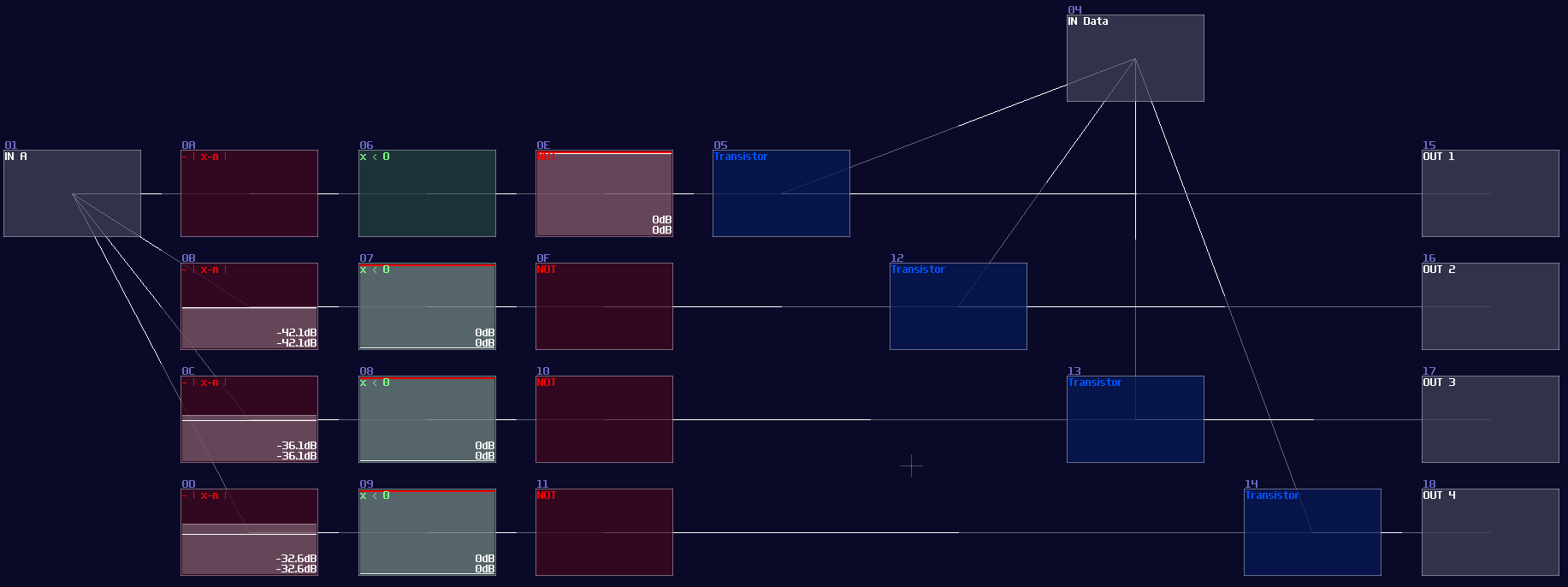
Owing to the logic gate configuation, you may directly covert the circuit into SunVox modules:
However, it is not an efficient way to build a decoder, since the number of logic gate will be increased exponentially when you add a new input. Normally, I use integer as my input signal for decoder instead, so you can reduce the complexity of modules from \(O(n^3)\) to just \(O(n^2)\) (I have borrowed a concept from computer science, called Big O notation, to describe how well the design can be scaled.)
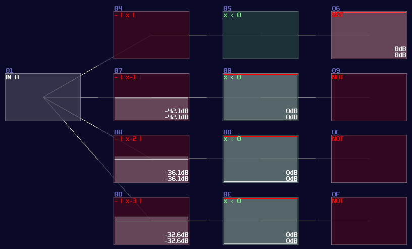
To build integer based decoder, you need a negative detector, an inverted NOT gate, and a specific function for an amplifer:
\[ y = |x - n|\text{ , where n is the nth of output} \]
To create such function, you may set the amplifier as the following:
| Controller | Values |
|---|---|
| Absolute | On |
| DC offset | -n (for each nth output) |
Once you have completed the configuration, you need to connect the module into the following order:
Input -> Customized function -> Negative dector -> Inverted NOT gate
After you have completed the chain and duplicated the chain parallelly, you will complete yourself of an interger based decoder. Feeding a positive DC signal at the input, generated from an amplifier, will change the selection of the output:
You may find it familar, and you may have seen it before. You are absolutely correct becuase this is the exact same decoder I have used in my old arppeggiator, used for counting the voices and selecting a specific pitch. Now you have finally understand how one of the vital components work in my arpeggiator!
Conclusion
That's about it, you have learnt how to build your own decoder and encoder for your modules, and I will tell you how to based on the similar concept to build multiplexers and de-multiplexers.
Example Project:
Multiplexer and Demultiplexer
Overview
Building a Multiplexer or De-multiplexer is not that difficult because you can build upon a decoder, so in this tutorial, I will teach you how to build such circuits.
Multiplexer
Multiplexer can let you choose a input signal path for the output, just like a HDMI switch which you can select a specific HDMI input for your screen.
Here is the truth table for a 4 channel multiplexer, since there are quite a few combinations, I only show the most important state for this circuit. I will put an X in the table, which means “don’t care”, meaning that the input will have no change neither 0 nor 1:
| In A | In B | In Ch0 | In Ch1 | In Ch2 | In Ch3 | Out |
|---|---|---|---|---|---|---|
| 0 | 0 | 0 | x | x | x | 0 |
| 0 | 0 | 1 | x | x | x | 1 |
| 0 | 1 | x | 0 | x | x | 0 |
| 0 | 1 | x | 1 | x | x | 1 |
| 1 | 0 | x | x | 0 | x | 0 |
| 1 | 0 | x | x | 1 | x | 1 |
| 1 | 1 | x | x | x | 0 | 0 |
| 1 | 1 | x | x | x | 1 | 1 |
Let me build a simulation to see the circuit in action:
"Wait a minute, is that just a decoder with an extra input?" Yes! All you need is an extra AND gate for your data stream of each channels, and an OR gate to return the selected stream, and... You are done, a multiplexer!
It is even clearer to see the decoder in SunVox, as you only need to attach a modulator after the output of the decoder, while the modulators act as transistors, controlling the flow of the data stream channels:
Demultiplexer
Instead of grouping multiple channels into one, de-multiplexer assign a single data source into one of the multiple destinations.
| In A | In B | In D | Out Ch1 | Out Ch1 | Out Ch2 | Out Ch3 |
|---|---|---|---|---|---|---|
| x | x | 0 | 0 | 0 | 0 | 0 |
| 0 | 0 | 1 | 1 | 0 | 0 | 0 |
| 0 | 1 | 1 | 0 | 1 | 0 | 0 |
| 1 | 0 | 1 | 0 | 0 | 1 | 0 |
| 1 | 1 | 1 | 0 | 0 | 0 | 1 |
Unsuprisingly, you can also see a decoder here for select the destination channels, meaning that if we reverse the I/O from the multiplexer, we can get a de-multiplexer like shown:
SunVox implementation:
Conclusion
Decoder is vital for digital logic since you can create other combinational circuits from expending the decoders. In the chapter, you have learn how to build multiplexer and de-multiplexer for dynamically routing the signal. After that, we will move on to other type of circuit, the fully featured adder.
Example Project:
Adder With Carry
Overview
Although we have learnt how to do addition, some other features - such as carrying and borrowing - are missing; these features are important since we can use them for limitating a range of numbers or spliting the number into serval digits for display. Thus, I am going to show you how to achieve other feature for additions.
Adder
In digital logic, we must build a full adder to compute any given two number; full adder works with two XOR Gate which one of them handles the two inputs and another XOR handles the carry bit with the calculated result. There are AND Gates too for handling carry bit for the next bit. Here is the single bit of full adder:
Single bit of full adder is useless because it can only calculate number between 0 - 3 (including the carry bit), so we always cascade multiple of them to perform larger numbers like shown which is a 4 bit adder:
Clearly, this is not a good solution for SunVox because we will end up using a lot of logic gates for such a simple operation; thanks to the amplifer, we can do addition in an analog manner by adding two incoming signal, while you can also apply a negative detector to check if the sum of two numbers are larger then the base (based 10 for the upcoming example) so that to perform carry logic by removing the sum to the sum output and sending 1 to the carry output:
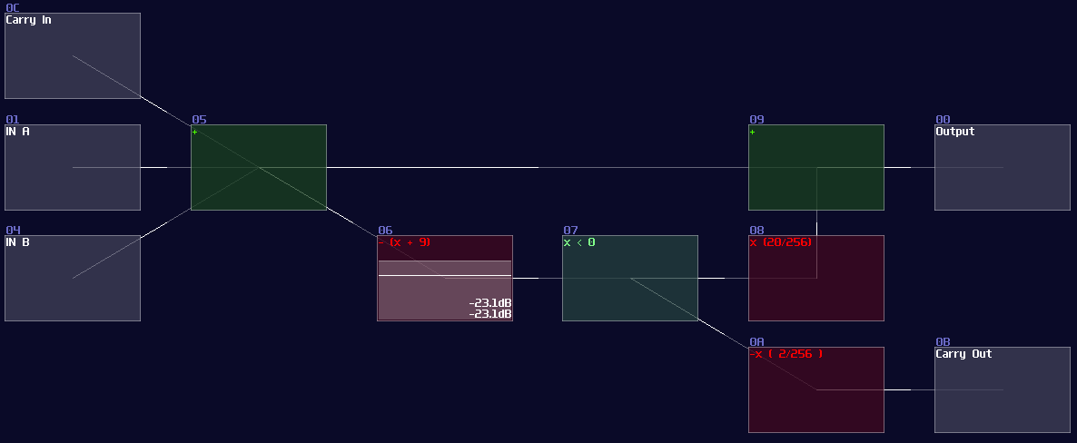
This adder works in any bases, so you can change Module 06 to trigger the carry logic in other amount, which can be octal, hexadecimal and beyond. MOdule 08 also required to change as well, to ensure the carry logic completely cancelling the sum output; the equation for cancelling is shown:
\[ (base \times 2) / 256 \]
If you work on decimal system, set the volume to 20, likewise setting the volume to 32 for hexadecimal, or 24 for base-12.
Example Project:
ADC and DAC
Overview
In some situations, it is more connivent to process data either in integer or binary form, while the input is not always the one you prefer; therefore, we need to know how to convert the data type to each others.
DAC (Digital to Analog Conversion)
If you want to compact your binary signal into DC offset, you can use a DAC. To convert the signal, it is better to normalize your binary signal either 1DC unit or 128DC unit, to make conversion easier.
If your input use 1DC unit, you may use the gain control to regulate the binary signal, which the gain value is \(n^2\) for nth bits:
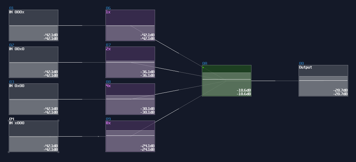
For 128DC input, you may tune down the volume to \(n^2\) as shown:
Both of the configurations also aligns to the DC offset of an amplifier, so consider the configuration above, both of the DAC will generate a signal with magnitude of 15DC unit.
ADC (Analog to Digital Conversion)
There are two ways to do ADC:
traditional method
The traditional method uses a negative detector and a negative constant for a threshold checking; because of the negativity, the detector is always on, unless the value of the input is large enough for a cancellation; once cancelled, the negative detector disabled, flipping the NOT gate to the ON state as a output.
Meanwhile, if the NOT gate (output) is true, it triggers the Modulator, passing the negative constant into the addition block, for finding the remainder after satisfies the output of the current bit; otherwise, the constant won't be added for the reminder, passing the original input into the next stage.
The configuration above is used for detecting the MSB of an 8bit integer, due to the magnitude of -128DC unit. To build the complete ADC, you must know:
- The upper bound of your integer
- The initial constant of the MSB
In the example, I decided to build ADC with the operation range between 0 - 10. Since I know the maximum is 10, I must pick a bit size that covers the maximum, using this equation: \[\text{Maximum} \le 2^x - 1 \text{ , where x = bit depth}\]
1, 2, and 3 bit don't work because the maximum values are 1, 3 and 7 respectively. Anything no less than 4 bit works, but we should pick the minimal bit size to prevent wasting resource on CPU usage. Thus we should settle down with 4 bit.
Once we know the bit depth of the signal, we can now find out the initial constant by using the following equation:
\[ \text{Initial constant} = 2^n \text{ , where n = index of MSB, start from 0 from LSB}\]
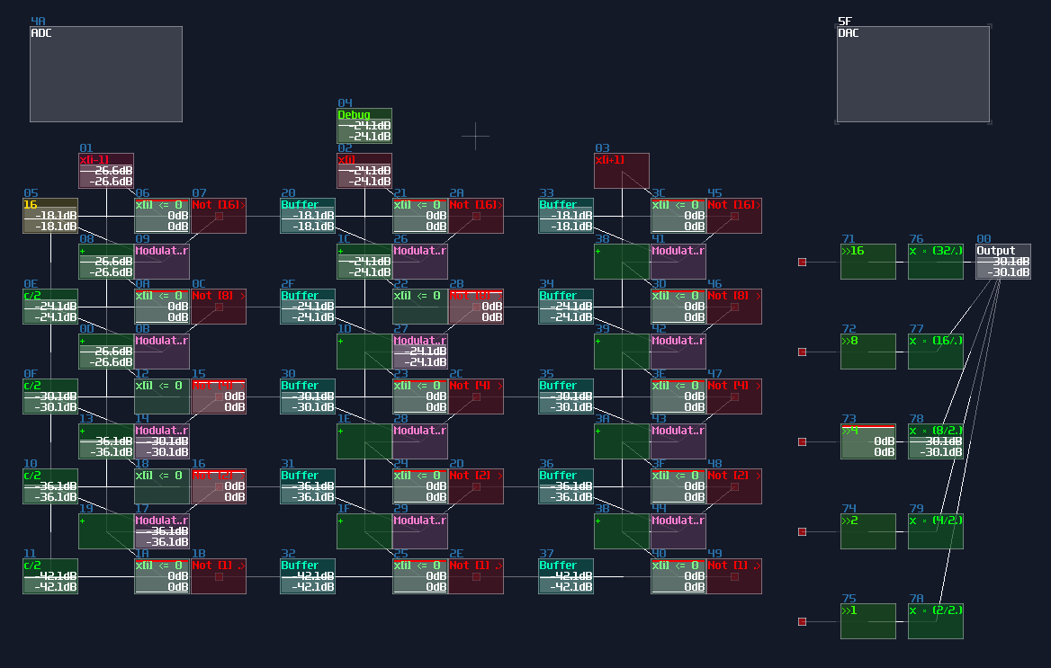
Since we have 4 bits, counting from 0, the index of MSB is 3; hence, the initial constant is 8. After that, we can cascade multiple detector stages, connecting the sum block of the current stage to the sum block and negative detector of the next stage; meanwhile, it is not necessary to define every constant for each detector stage, as binary number digit always have half a value relative to their left digit; thus, we can squarely and recursively divide the initial constant by 2 for each stage, ending with the configuration below:
Waveshaper Method
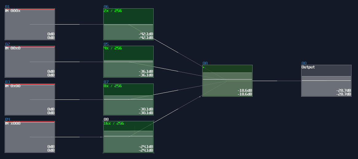
Rediscovery of wavershaper properties is a boon for logic processing, as it has simplified a lot of circuits and has achieved some modules that is thought to be impossible. If you work on a ADC with the range less than 256, waveshaper is a quick and (slightly more) efficient way to build such structure.
Like previous design, I use a 4 bit adc as an example; all you need is 4 waveshapers and the following configuration:
| Controller | Values |
|---|---|
| Input vol | 256 |
| Mix | 256 |
| Output vol | 256 |
| Symmetric | off |
| Mode | LQmono |
| DC blocker | off |
For the waveshaper curves, you need an alternating pattern for each bits, which the off state is at 0, while the on state is either -1 or 1, depending on your application. Each digits have its own independent frequency for parsing binary numbers, which the next left digit always half the frequency to the current digit:
At bit 000x (LSB):
At bit 00x0:
At bit 0x00:
And so on. Generate these curves requires curve generators, which is included in SunVox. Pixilang is required to run the program.
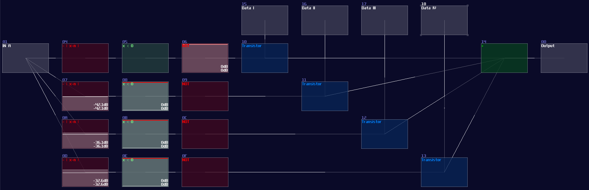
Once your curves are ready, simply connecting the input to the waveshaper to complete the ADC; however, due to the performance concern, waveshaper disables its output after a certain time when the input is 0. The work around of this issue is to attach a modulator in between the input and the waveshapers, with applying a constant +128DC input for the modulator to prevent the timeout. Thus, we will have a ADC like shown:
Examples
ADCs are common in my contraptions. In Game of Life module, if you open the life detector module, you will immediately see a group of ADCs, used for breaking down the input into individual cell state, and DAC if you switch the project to layer 3 to summarize the result:
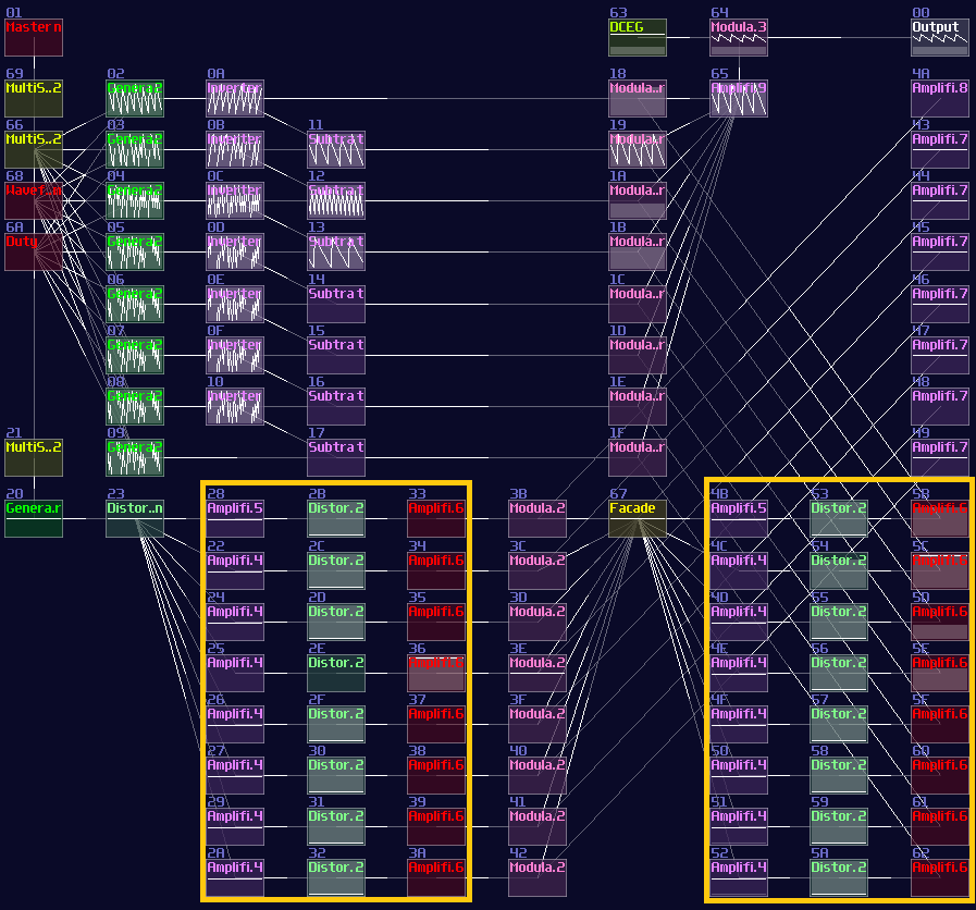
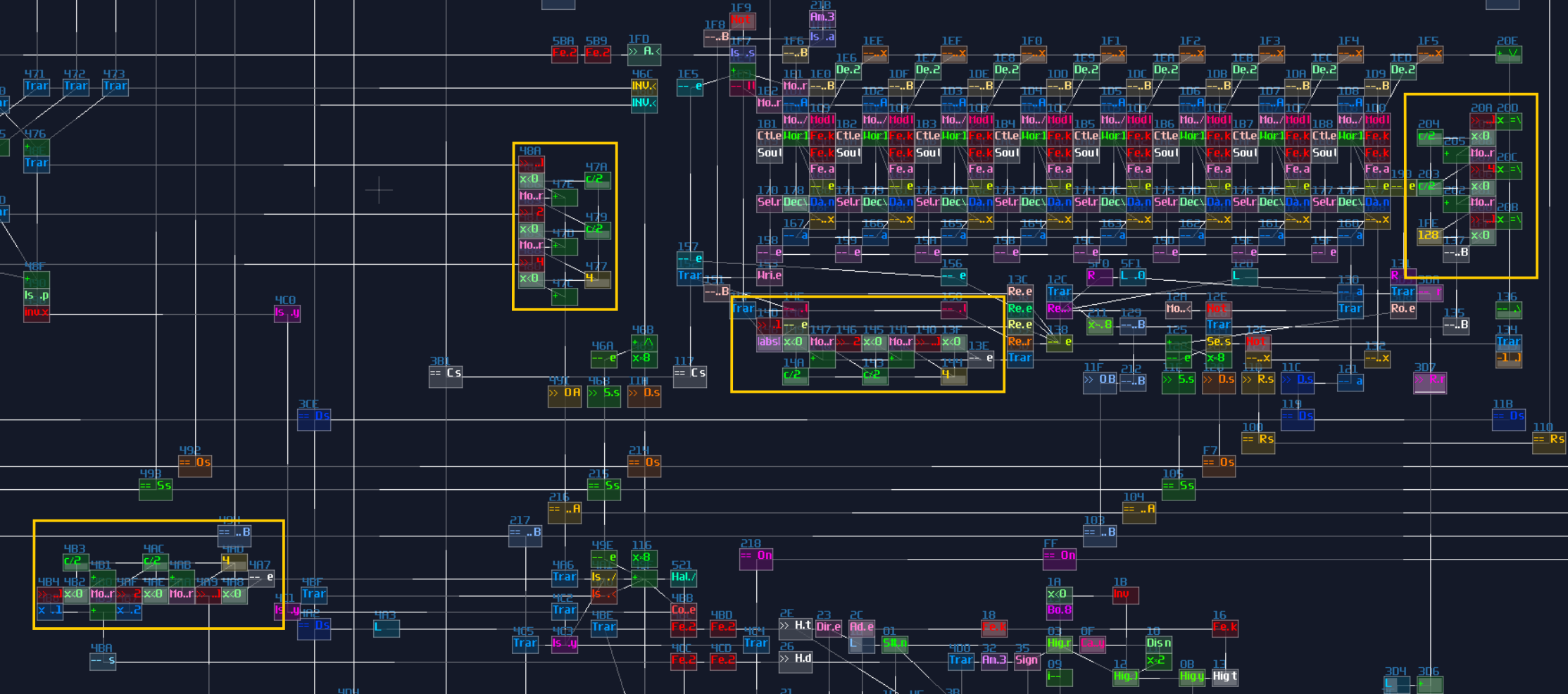
VOXCOM 1610 is even wilder, as you can see ADCs everywhere, for splitting the operands due to different indexing or operation modes:
Conclusion
Now you know how to build ADC and DAC for you projects, and you have seen that they have many applications. For the upcoming chapters, will start to learn memory circuits, but before that, let's take a break with a checkpoint, and practice the things you have learnt.
Examples Projects:
Checkpoint A
Congrats! You have reached the first checkpoint of the 3xLog. Now you have learnt the basics of the digital combination logic and its SunVox implementation. Before moving on to the more complex stuff like memory circuits and state machine, you may do these riddle to practice what you have learnt. I will order them by difficulty. It is recommended to do all of the introductory and easy level first if you want to actually build something on SunVox. In addition, let me share the logic processing modules, so that everyone can use it out of the box.
3xLog Tool kit A - Logic Gates, Sources and Maths:
Here are all the commonly used building block for the combinational logic circuits. Some of them are basically the default modules, but they save you some pain aligning the color coding and naming conventions. Feel free to grab it and mess around it!
3xLog Tookit - Gates and Numerical Operators
All the example projects in the section:
Input and Clock Logic Gates Bitwise Operations Basic Numerical Operations Long Division Newton's Method Compressor vs Waveshaper Base Newton's Method Trigonometries Monostable and Pulse Extender Encoder and Decoder Monostable and Pulse Extender Adder With Carry ADC and DAC
Memory Circuits
Now you have some basic understanding to simple components, so we can now move on to more complicated stuff. In the following chapters, you will know about the basic of memory circuits, to store your data in your modules, both permanently or temporarily.
In practice, you would less likely to use the mechanisms in chapter C, unless you make generative music or presets modules.
As usual, I will post some of the modules, so you can play around it out of the box.
SR Latch and Flip Flop
Overview
Let's start from the simplest memory, to see how SunVox store a single datum, using SR Latches and Flip Flops.
Feedback loops
I guess many of you have faced a problem using feedback where it get infinitely loud, producing unpleasant noise that hurts your ears, and distorting your output signal:
Although an unstable feedback is bad for music production which it produces a lot of unwanted noise and ruins your mix, this is good for Logic processing because the feedback signal retains the input state; however, we need to solve some issues:
- How to get a clean readout?
- How to make it feedback loop more stable?
- How to reset the state of a memory?
Without solving these problems, the memory circuit would be useless since we can't control the state at demand; thus, we need to take a step further.
SR Latch
The simplest practical memory circuit is a SR latch. It has two inputs which one of them is used for switching the memory to ON state, while another one switch it of. When none of the input has switched, the latch retains the current state. It is invalid to switch on both of the input since it can be any state, depending on the components and environments used for the circuit, causing ambiguity that make this particular state useless for any application.
| IN S | IN R | OUT | OUT Inverted |
|---|---|---|---|
| 0 | 0 | retains prev state | retains prev state |
| 0 | 1 | 0 | 1 |
| 1 | 0 | 1 | 0 |
| 1 | 1 | ? (invalid) | ? (invalid) |
In the real world, SR latch is simple which only a pair of NOR gates (or NAND gates) are required; to form a feedback loop, the output of a NOR gate is connected into the input of another NOR gate, likewise for the other NOR gate. After that, two NOR gate will remain a single input, and this is where the set and reset input located:
In SunVox, we can create a SR latch by expending from the feedback loop I have shown you before. To make it more stable, we must feed a clean DC signal, so I have used an analog generator based DC source for demonstration.
"Wait... why is there a distortion module appeared out of nowhere? What is the purpose of it?" The distortion has some modification which it has a bit depth of 2 and the volume is doubled. This configuration can prevent the feedback loop going out of bound, as you can see:
Awesome, now we have a way to store a single bit reliably, but we need to clear the state. To do that, we have two options:
The first method is to use a modulator based transistor, connecting from an NOT gate for the reset input and the feedback module, connecting to the amplifier that forms a feedback loop:
This works because the NOT gate retains the Feedback loop, unless the Reset input is ON for shutting off the NOT gate resulting in breaking the loop.
Alternatively, you can use a sound2ctl module to control the volume to one of the feedback modules. To retain the loop, you must set the min controller to max, and vice versa to the max controller to the sound2ctl, to switch OFF the memory by feeding the reset signal:
Either way should work like a SR latch.
SR Flip Flop
Instead of trigger the memory with the level of the signal, you can convert it into flip flop by attaching and gates at the inputs with Mono stable circuit to receive clock signal, making it triggering on the edge of the signal. (Falling edge monostable is used for the example):
Conclusion
You have learnt how to build the simplest memory circuit in SunVox for storing a single state, but we can do better from that, so for the following chapters, I am going to introduce other memories and tricks to make data storage more efficient.
Example Project:
JK Latch and Flip Flop
Overview
Despite not used in SunVox due to its questionable behavior, let's see how other solve the problem in SR latch by building a JK flip flop.
JK Flip Flop
To overcome with the invalid state, an electrical engineer named Jack Kilby invented a universal Flip Flop.1 Based on his own name, this flip flop solves the wasted invalid state, replacing with a toggle function as shown:
| IN J | IN K | OUT | OUT Inverted |
|---|---|---|---|
| 0 | 0 | retains prev state | retains prev state |
| 0 | 1 | 0 | 1 |
| 1 | 0 | 1 | 0 |
| 1 | 1 | toggle | toggle |
This is a step forward to a better flip flop since the additional toggle function is useful for switching a device using a momentary switch, or used for building counter; despite its flexibility, this flip flop doesn't made into SunVox, as there are some inconsistent behavior for this device.
- Racing condition
How this flip flop works during the toggle state is that the flip flop intends to oscillate in a high speed, but the clock limits the oscillation, acting like it is toggling ON and Off. There is workaround, but I never use this flip flop in practice because there are two more simpler and more practical alternatives for any applications in SunVox, and I will tell you about that soon.
Reference
D Latch and Flip Flop
Overview
Since JK flip flop is too complicated and fills with racing condition, I usually use the alternatives to get the job done; in this chapter, I will go through how to build a D latch and flip flop so that you can use it for storing handful of data for your modules.
Concept
If we expend the SR latch with two AND gate and connect a pair of input to each of the AND gate, while one of the input of an AND gate of an input pair has a NOT gate, we can build a D latch:
Unlike SR latch or flip flops, it have a data input (D) and an write enable input (E). Write enable input is used for locking the memory state when the enable input is off, and it is used for changing the state of the memory based on the data input when it is on:
| IN E | IN D | OUT | OUT Inverted |
|---|---|---|---|
| 0 | x | retains prev state | retains prev state |
| 1 | 0 | 0 | 1 |
| 1 | 1 | 1 | 0 |
D FLip Flop has an identical structure to D latch, except that the enable input will be edge triggered instead of level triggered.
Building D Latch / Flip Flop from SR Latch
You can simply convert a SR latch into a D latch; instead of connecting the two input into the transistor and the "+" module, an additional pair of AND is added in between the input and the aforementioned destinations. According to the circuit diagram, one of the D input requires a NOT gate for toggling the data:
Likewise, you can convert it into a flip flop by inserting a monostable circuit at the Enable input, as shown:
If you have done right, you will have a D latch / flip flop for storing a single bit.
More Efficient Approach
"IT IS STILL TOO LARGE! WHO WOULD EVEN USE THIS INEFFICIENT DESIGN TO STORE A SINGLE BIT, WITH 20MS OF DELAY?!"
I can definitely hear people screaming that, but the previous design is just a proof of concept which it has not much value to practical application other than teaching how things works.
To make a better design, we need to play around three modules:
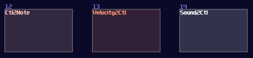
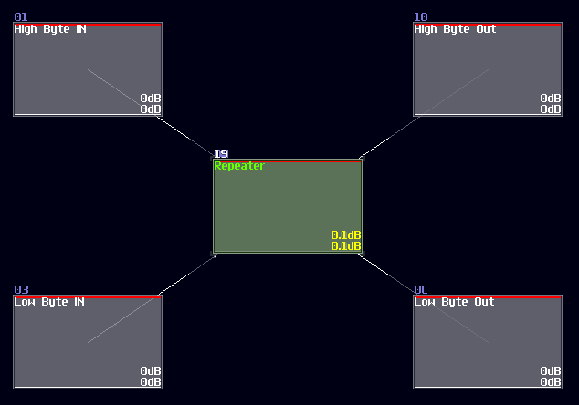
Velocity2Ctl is a powerful module if you pair it with an amplifier, as the Veclocity2Ctl can control the DC offset of the amplifier by sending a pulse of midi signal, and the controller signal retains even the midi is OFF. This leads to a much more compact memory design because it can let us store a byte of data without actively refreshing the memory, while the write and clear sequence are much simpler and much more reliable.
However, you can't squarely use the Velocity2Ctl because it only accepts midi rather then a DC signal; therefore, this is where Sound2Ctl and Ctl2Note come in. Sound2Ctl convert the DC signal into control signal, and we can use the control signal to manipulate the velocity of Ctl2Note so that for every ON state to the Ctl2Note, sending a midi signal containing a velocity magnitude alining to the DC offset of an amplifier which has a 8bit combination.
Thus, we need to form a chain:
Ctl2Note -> Veclocity2Ctl -> Amplifer
for the core memory part, where the setting of the modules are shown:
Ctl2Note:
| Controller | Values |
|---|---|
| State | off |
| NoteOn | on pitch change |
| NoteOff | on min pitch |
Velocity2Ctl:
| Controller | Values |
|---|---|
| On NoteOff | do nothing |
| OUT min | 0 |
| OUT max | 32768 |
| OUT offset | 0 |
| OUT controller | 3 (controls DC offset) |
While the Amplifier is the default setting. After the core part is complete, we need to find a way to control the memory, so we use two Sound2Ctl to controlling the the velocity and state respectively:
Sound2Ctl from Input D
| Controller | Values |
|---|---|
| Sample rate | > 256 |
| Channels | mono |
| Absolute | off |
| Gain | 256 |
| Smooth | 0 |
| Mode | LQ (No interpretation) |
| OUT min | 0 |
| OUT max | 32768 |
| OUT controller | 6 (controls velocity) |
Sound2Ctl from Input E
| Controller | Values |
|---|---|
| Sample rate | > 256 |
| Channels | mono |
| Absolute | off |
| Gain | 256 |
| Smooth | 0 |
| Mode | LQ (No interpretation) |
| OUT min | 0 |
| OUT max | 1 |
| OUT controller | 7 (controls state) |
After you have attached the two Sound2Ctls, along with a Monostable at the Input E, you have completed yourself a D Flip Flop, which the final result should be looked like this:
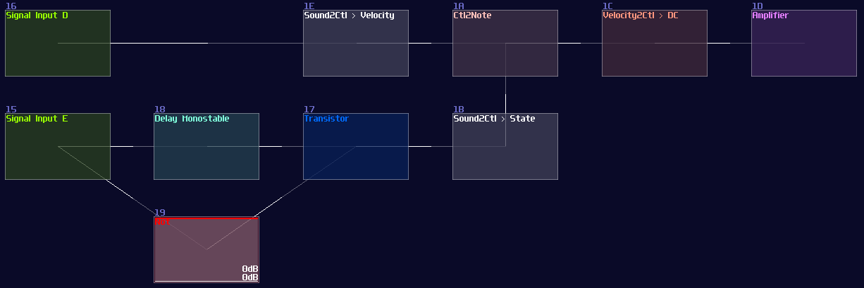
Keep in mind that the choice of sameple rate is important because your flip flop must be responsible enough for your application, but setting the sample frequency to the maximum is not a wise idea since it might take too much CPU usage once the number of D flip flops scales up. 256 hz is generally a good start because most of the system can't work faster than 50 hz due to the feedback delay.
Conclusion
We have finally know to to store a byte using D latch and D flip flop, and we can now implement a more efficient design with an aid of midi signal. For the upcoming chapter, we will see how we can use D flip flop to create another type of flip flop.
Example Project:
T Flip Flop
Overview
In this tutorial, I will show you how to build a T flip flop expanding from a D flip flops:
Concept
Don't fooled by its simplicity; although T flip flop only have one job and it looks simple on the surface which its job is flicking the output ON and OFF for every clock trigger, it is actually an expansion from a D flip flop.
| IN T | OUT | OUT Inverted |
|---|---|---|
| 0 | retains prev state | retains prev state |
| 1 | toggles | toggles |
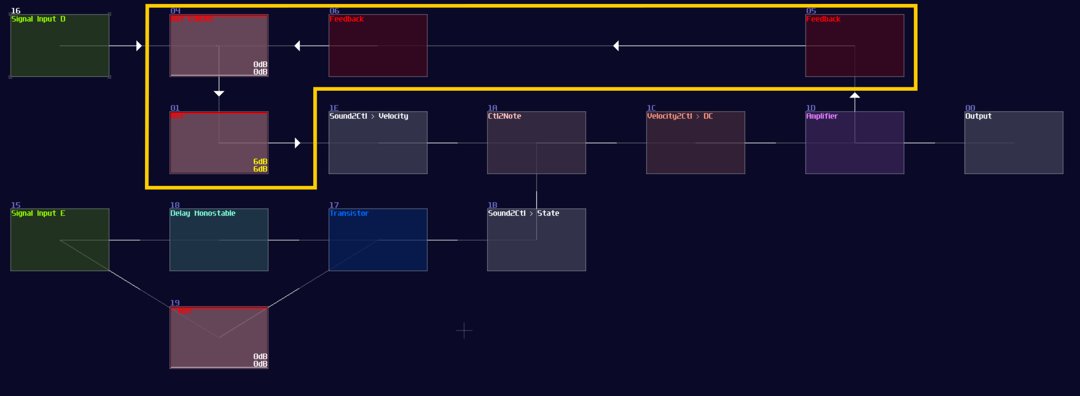
To make the D flip flop "flips" the output signal, a XOR gate is attached before the input D of a A flip flop; using the output of the flip flop, it loops back to the input of the XOR gate. Because of the XOR gate, if the output is True, along with the input T, the XOR gate returns False for the D flip flop, resulting in switching OFF after a clock update, and vice versa if the D flip flop output is False:
T flip flop from D flip flop
As you can see, it is easy to convert a D flip flop into a T flip flop; an additional XOR gate (Chain of two NOT gates) added before Sound2Ctl that controls velocity, where the XOR gate take the output from the flip flop along and an input for triggering the flip flop:
Now you have a T flip flop; however, it is not the best solution, because of the use of feedback module. To break the 50 hz limitation, we need to know a feature in Multisynth. If you set the Trigger mode in the multisynth, the multisynth will only toggles the state of a midi note on key press and ignores the off state. If we attach a generator generating a DC offset after the multisynth, we technically just built a T flip flop; nevertheless, there is a challenging task since there is no way to reset a state of a multisynth unless we press the stop button. Or do we?
Thanks to the discovery by offthesky1. There is a solution to this problem. Let’s take a quick look to the phase option of the multisynth. We know that phase parameter can change the phase of a waveform or a starting point of a sample, but how about the project inside the metamodule?
The answer is: you can change the play head of a project proportional to the phase. For example, if you want to play at the perfect middle of a project, you can set the phase at 16384. By using this trick with command 30 to stop the play back of a project, you can set the play back conditionally.
To build a re-settable T flip flop, you need to build an internal flip flop with two play back entries using a 4 line pattern:
Line 0 – Enable toggle mode to the input multisynth;
         set the generator to full volume;
         plays a note

Line 1 – Stop the project by using command 30;
         stop playing the note

Line 2 – Disable toggle mode to the input multisynth;
         set the generator to 0 volume;
         plays a note

Line 3 – Stop the project by using command 30;
         stop playing the note


The Tracker command should looks like this:
0: ----017c000001 ----0201008000 C5--01--------
1: ------0030---- -------------- ==------------
2: ----017c00---- ----020100---- C5--01--------
3: ------0030---- -------------- ==------------

Where Module 01 is a Multisynth, while 02 is a Standard Generator (NOT ananlog).
Once the pattern is completed, connect the multisynth to the generator connected to the output.

Once you have the internal structure, save the project as a metamodule, so you can change the play back position.
To control the internal flip flop, you need a multisynth so that to redirect all inputs into a single point. As usual, you need Ctl2Note modules; to prevent race condition over the state control of a single Ctl2Note, you need two of them, handling the T input and the reset control independently.
Each Ctl2Note modules require a Sound2Ctl to update the state, and they have the identical configuration:
| Controller | Values |
|---|---|
| Sample rate | > 256 |
| Channels | mono |
| Absolute | off |
| Gain | 256 |
| Smooth | 0 |
| Mode | LQ (No interpretation) |
| OUT min | 0 |
| OUT max | 1 |
| OUT controller | 7 (controls state) |
After finished the pair of sound to midi group, you can now work on the input ports. As usual, the T input requires a monostable circuit like the other flip flops, to trigger the flip flop at the edge of the signal.
For the reset part, since the final module uses controller to reset instead of an audio signal, this part is triggered by level rather then edge of the signal. Thus in this example, an amplifier is used for the switch (see ## Reset), which is just a default amplifier module, with controlling the inverse function. To make the switch function and reset in the right time, a -128DC signal, along with a delay is feed for the switch. The switch connects the reset side of the audio to midi group, and an additional Sound2Ctl to change the phase of the flip flop with the configuration like shown:
| Controller | Values |
|---|---|
| Sample rate | > 256 |
| Channels | mono |
| Absolute | off |
| Gain | 256 |
| Smooth | 0 |
| Mode | LQ (No interpretation) |
| OUT min | 0 |
| OUT max | 16384 |
| OUT controller | 7 (controls phase) |
If everything is right, you can produce the following structure:
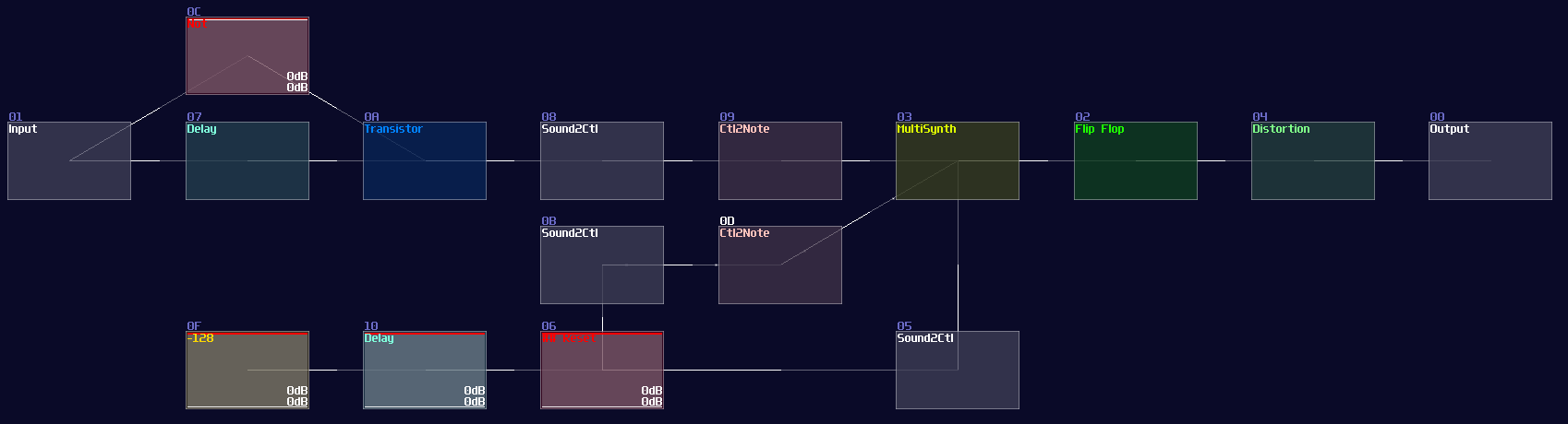
How it works is that when you send a pulse into the input T, it plays the first two lines of the internal flip flop, setting the MultiSynth into toggle mode and toggle the multisynth and the nearby generator ON and OFF. When you flick the result switch, it sends another midi signal with playing at the middle of the pattern inside the internal flip flop, temporarily removing the toggle mode and send a silent note to switch the generator OFF.
Owing to the imperfect DC signal from generator, you need a distortion to normalize the signal.
Conclusion
There you have it, you have learnt about how to convert a D flip flop into a T flip flop, and its more efficient variant. These flip flops alone should be enough for various of application, but I will tell you another type of memory circuits.
Example Project:
reference
Delay Based Memory
Overview
Do you know anything with a delay and a feedback can be memory components? In this tutorial, I will go through some memory ideas using delay, echo and modulators.
Delay Line Memory
Replaced by solid state ram, Delay Line Memory is one of the oldest data storage, developed in 1949 for EDSAC1. How it works is that a signal is sent through a medium and the signal is detected by the receiver, while the receiver also connects to back to the medium, forming a feedback loop. Thus, using the timing difference of the pulse, we can access the data in a sequential way2.
There are a few types of delay memories:
Interal Feedback
Delay is the most common way to build a memory, using the feedback function:
| Controller | Values |
|---|---|
| Dry | 0 |
| Wet | 256 |
| Delay L | ANY |
| Delay R | = Delay R |
| Volume L | 256 |
| Volume R | 256 |
| Channels | ANY |
| Inverse | off |
| Delay unit | ANY |
| Delay mul | 1 |
| Feedback | 32768 |
Echo works similarly to the delay; in fact, this was the only way to build reliable memory storage before Ctl2Note because the older version of SunVox couldn't convert audio signal into midi, nullifying the advantage of MultiSynth and Vel2Ctl.
| Controller | Values |
|---|---|
| Dry | 0 |
| Wet | 256 |
| Feedback | 256 |
| Delay | ANY |
| Right ch offset | off |
| Delay unit | ANY |
| Right ch offset (delay/32768) | 16384 |
| Filter | off |
| F.freq | --- |
The delay time and unit can be any duration, as long as your application requirement; it is also optional to use stereo or mono for your memory storage for doubling the storage. To clear the memory, just set the feedback to 0; however, this way might cause long reset time when the delay time is long, but thanks to the new "xx" command, we can clear memory much more efficiently.
To build such memory, metamodule is required, and we need to contain a delay or echo module with the setting mentioned above, with exposing delay time and unit as controllers, setting the playback to ON without repeat.
Then we set the internal pattern as shown:
Line 1: XX--01-------- ------0030----
This will clear the feedback state of the module at instant if we play the pattern, and stop the play back immediately. To play the pattern in the metamodule, we can use the same audio to midi trick from T flip flop, sending a midi signal to the metamodule.
External Feedback
This kind of delay can have extendable delay time because it is not bound by the delay time of a single module, but the whole module chain. Besides delay and echo (only delay, no internal feedback), modulator also can be used if we set the modulation mode into phase absolute mode.
To build such memory, you just need to use feedback modules with your delay modules of choice. To reset the memory, you can set one of the module volume to 0, or wrap the delay feedback with a Metamodule with sending the "XX" command internally to clear the delay signal.
Here is a delay line memory with 16 second worth of capacity, using modulator; you may use other delay modules as well, as lang as the the internal feedback is 0:
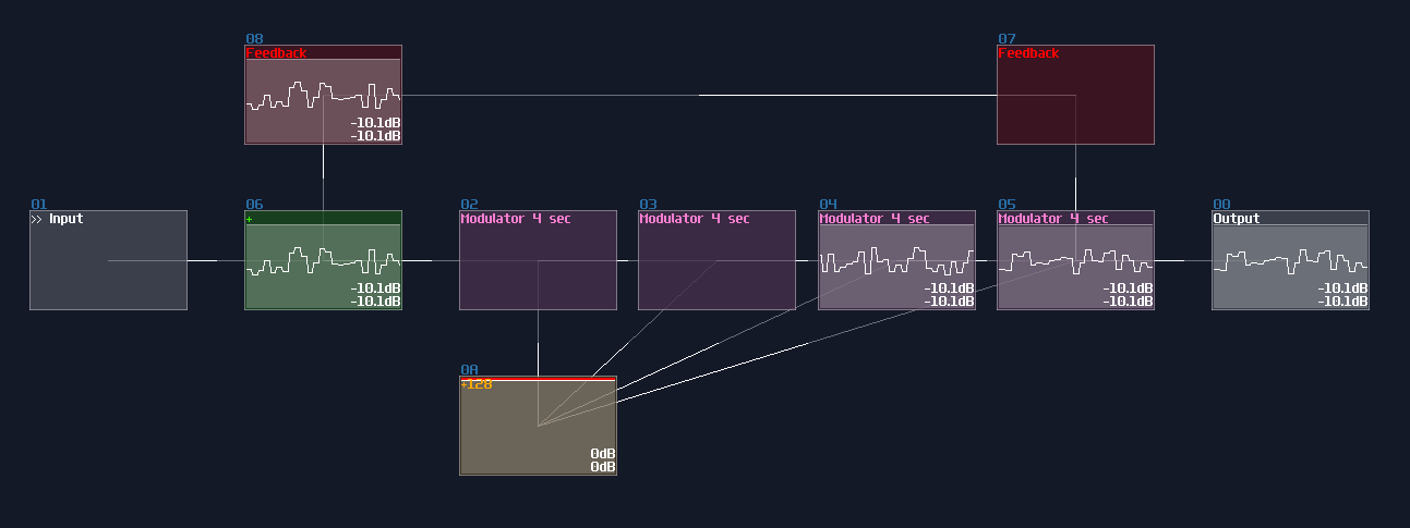
Application
Due to the sampling offset, the delay line might not be as clean as velocity based variant, but because of the higher capacity, these kind of memory circuits are normally used for rendering graphics by storing the graphical data, either in exact segment or the location of points:
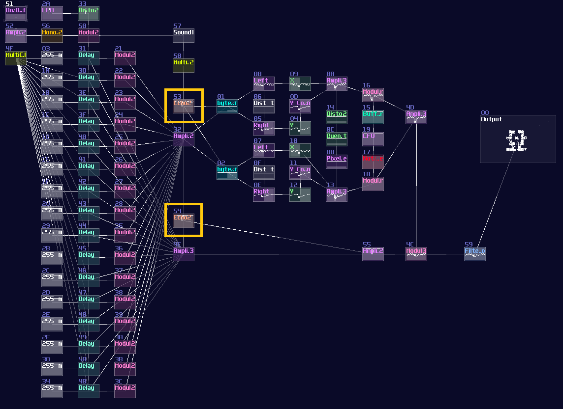
Accumulator (aka i++)
Besides audio or continuous signal, you may store a constant DC signal within a precise time. The simplest form of delay based DC storage is an accumulator, which it stores a stackable constant DC signal.
To build an accumulator, you only need a delay modules (or echo) with a Monostable. The timing of the monostable must be aligned with the delay time of the delay block; for example, if your delay module have a timing of 1 tick, your monostable circuit must be in 1 tick; otherwise, you may get some unwanted noise due to the imperfect timing. If you have memory cells insides a metamodule, make sure that the tempo is aligned with the master project.
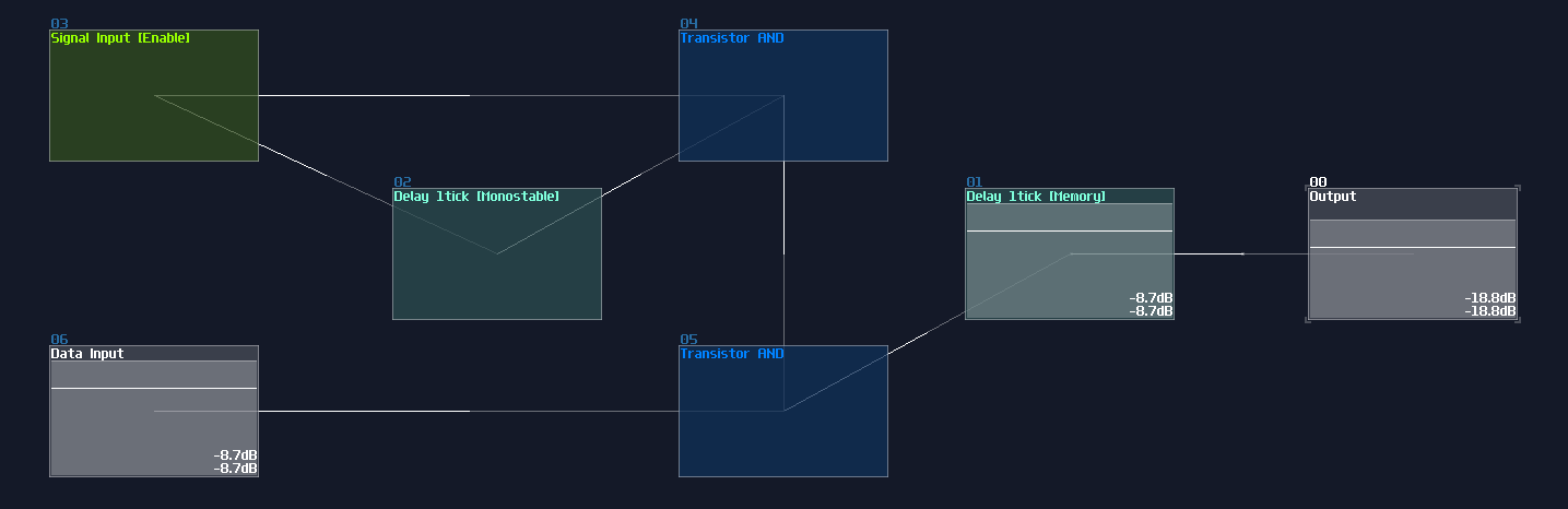
If you trigger the signal input module, it sends an write signal for the memory, writing with the amount of given input which can be a constant or a variable. Resetting the accumulator can be simply done by setting set feedback of the memory cell to 0, using Sound2Ctl.
Accumulators are useful for various application, including my score counter in my pong game:
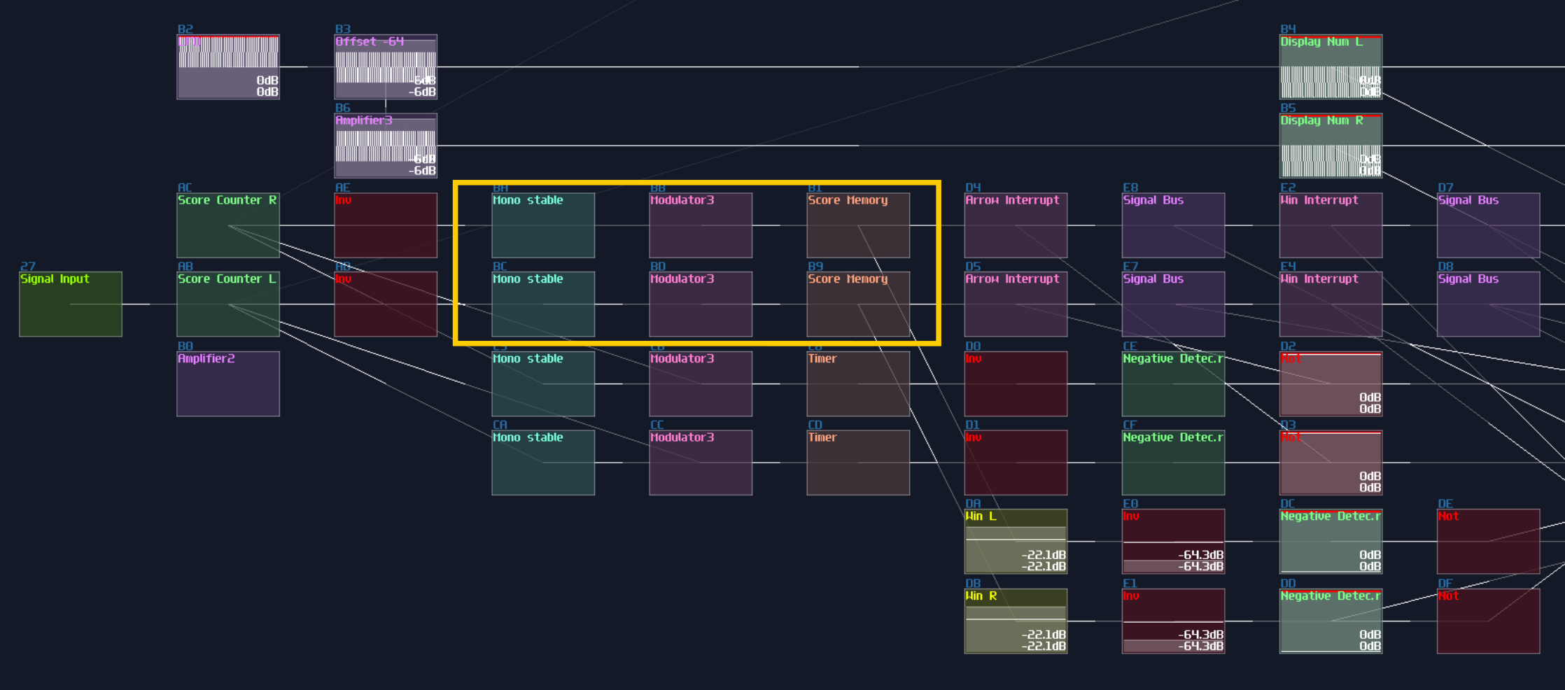
And the accumulator in my (and fuzion_mixer's) loudness meter:
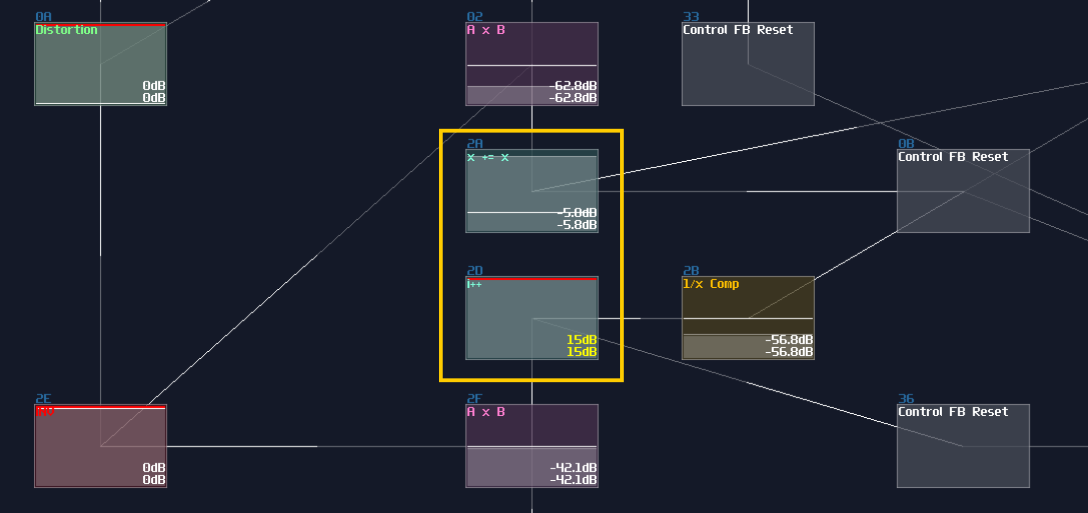
Old Style D Flip Flop
Instead of accumulating, you can clear the stored signal before writing the memory, to build a delay based D flip flop. The advantage of this method is that you can store any value with these kind of flip flop, to build memory circuits without the 8bit number limitation:
To overwrite the original data, you must clear the data by removing the offset or set the feedback to zero before adding a new value. To do that cleanly, you may wrap the delay storage inside a Metamodule, using the "XX" command for the delay storage, trigger by the Monostable impulse from the Enable input; the writing sequence is delayed by 2x unit of the Monostable impulse length, to prevent race condition.
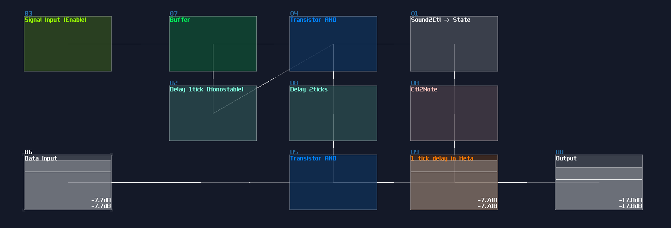
Due to the Ctl2Note, this kind of memory is rarely used, but it was common in my older prototypes because this was to only way to build flip flops, so here is my old RAM design, using the same technique.
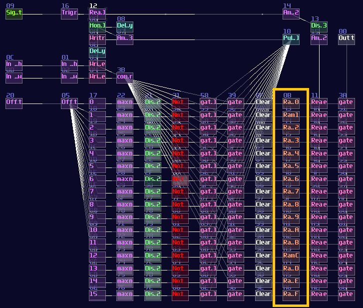
Simple Timer
Based on the accumulator, we can build a timer by setting the feedback to any non maximum or minimum value so that the Delay module can slowly (or quickly) fade the stored signal like an capacitor. To make it even more useful, inverter and negative detector can be used for normalizing the output signal:
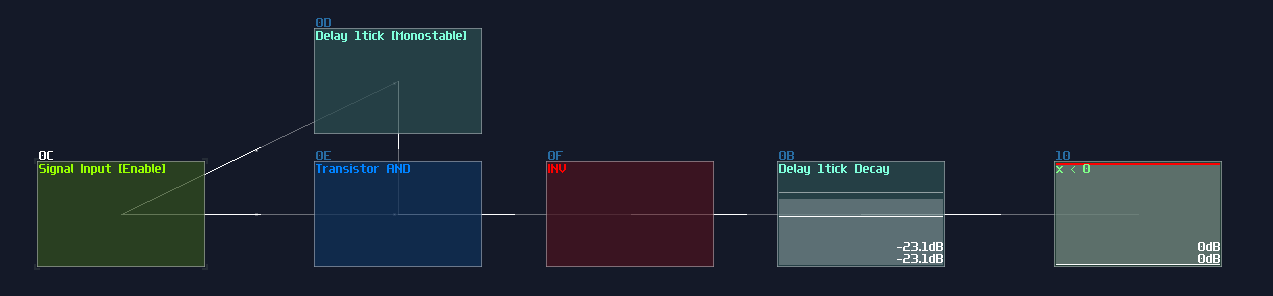
This was used for overriding with the flashing arrows for a short amount of time for my pong game; since the precision of timing doesn't matter, I squarely used the echo module as timers.
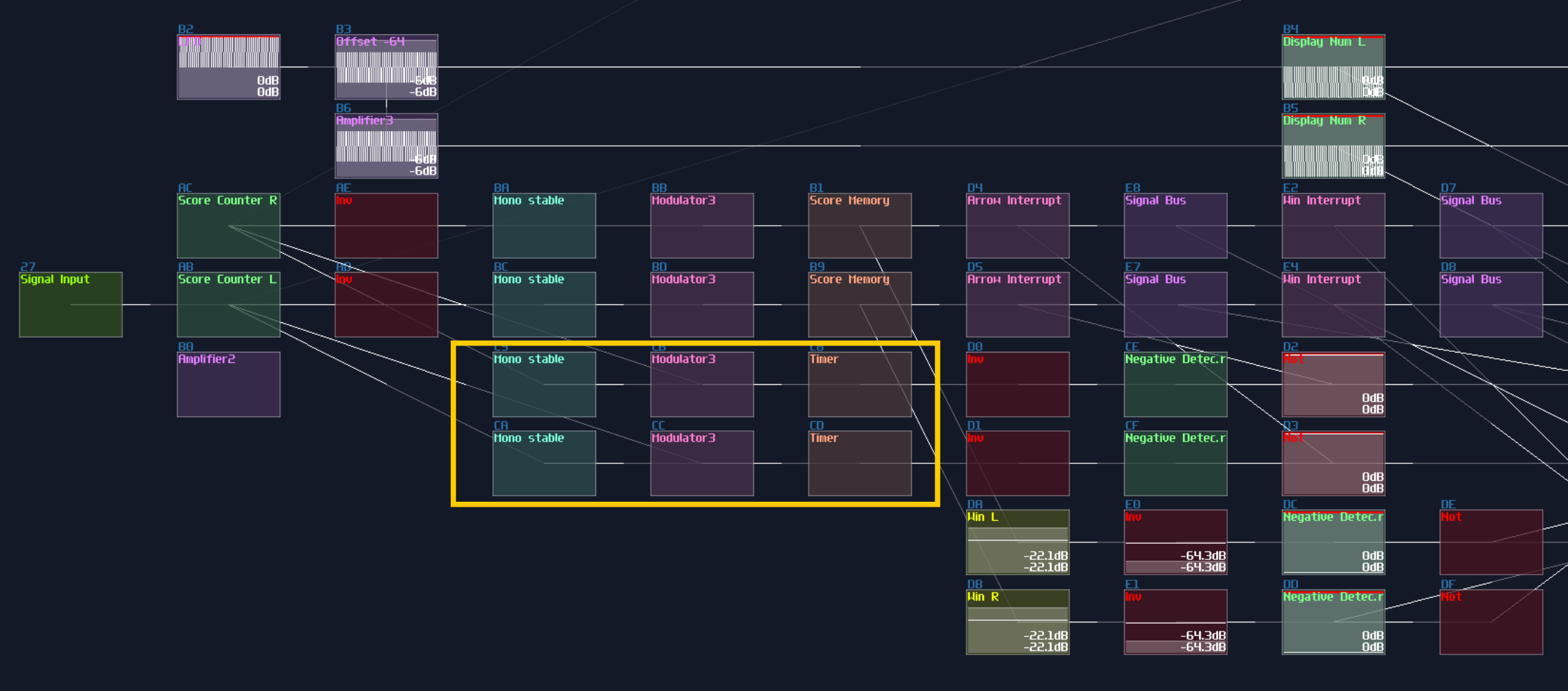
Conclusion
That's about all of my delay type module based memory, and you have also learnt the application behind these memories. For now, let's take a break because I will tell you about something different for the upcoming section.
Example Projects:
Delay Line Memory Simple Timer and D FLip Flop Counter
Reference
Checkpoint B
Great! Now you have completed this chapter, building memory modules for storing your data! Let's grab yourself my toolkit and test your knowledge over my riddles!
3xLog Tool kit B - Memories, Latches and Flip flops:
Here are my commonly used modules for basic memory storages, including a SR latch, D/T Flip Flops, and an Edge Triggered Counter. Some of the modules require two inputs, so you may use my two "Extract" modules to correctly convert the signals for the memory circuits. For the two input modules, they have a code prepended to the name of the module, with the convention of two channels separated by a slash "/". For example: D/CLK means the left channel takes the data, while clock signal for the right.
All the example projects in the section:
SR Latches and SR Flip Flop D Flip Flop T Flip Flop Delay Line Memory Simple Timer and D FLip Flop Counter
Graphics
Finally, we have reached the long waited topic, graphic in SunVox! You will know how to make basic shapes and geometry transformation.
This topic actually has no much practical applications since it requires many modules thus a high CPU usage; however, it is a good party trick to show off about your SunVox knowledge, showing others that you can build a fully functional seven segment display to show your calculations, or making oscilloscope music.
XY mode, points and pixels
Overview
Before you can do some cool visual, you must know the basics of how to config a screen for you module, and what is a point which is the smallest unit you can render.
Configuration
Before the magic happens, you must set your module visualization as the following:
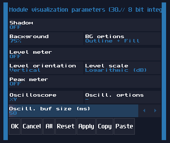
The most important of the setting is the Oscilloscope mode, which you must use the XY mode to print your image. The XY mode splits the channels into to two directions, where left channel move the X axis (left and right) while the right channel move the Y axis (up and down). The Oscill.buf size are also preferred to be the maximum so that the image would be the clearest. Level meter should be off; otherwise, you may see the level bar jumping, affecting the readability of the module.
A Point and a Pixel
It is simple to get a point from amplifiers by changing the DC offset which to point will move towards to the top right when the controller value is move towards +128, and vise versa when the controller moves toward to -128:
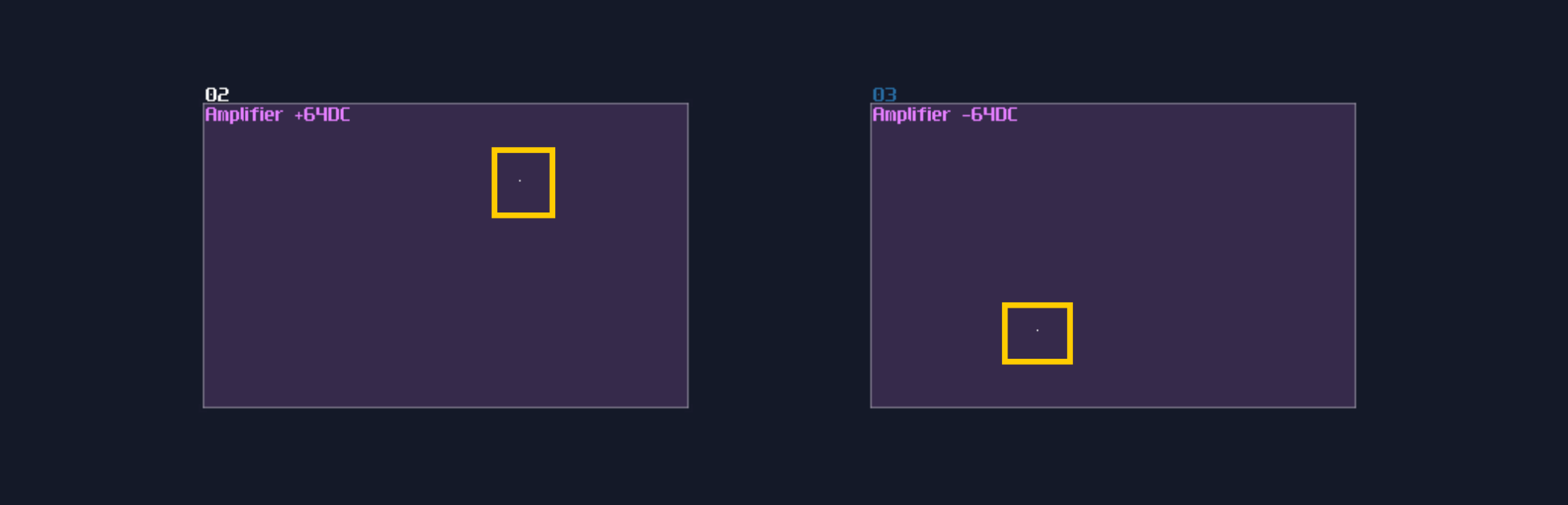
However, the default DC offset can only move the point diagonally, and it is impossible to travel places like top left and bottom right, which is pointless. Thus, to move the point freely, we generally use separate DC offset controls for each channels, filtered by panned amplifiers as shown:
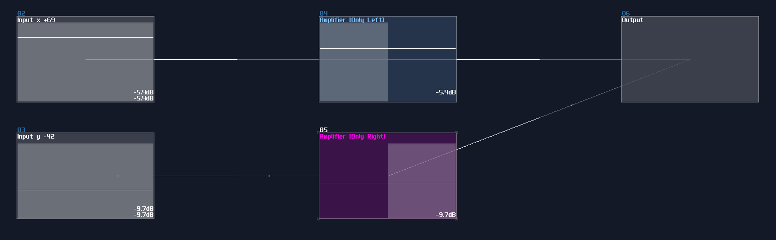
Cool, now we have a freely moving dot, but... it is way too small and it is hard read for many devices. In fact, the dot in the image above is so tiny that it is nearly invisible. For solving this problem, we can enlarge a dot by adding noise into the point, using distortion with noise sized by another constant DC offset from an amplifier. By summing the point location and the noisy square, we now have a larger "pixel" for your display.
![]()
Similar concept can be found in the display driver of the Game Of Life Module so that the module can present the 5x5 gird clearly:
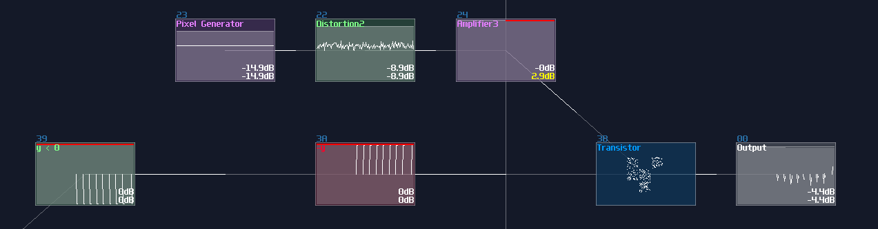
Conclusion
Now you know how to config your module to display things and to render your first pixel, for the upcoming chapters, you will learn about how to achieve vector graphics, from line to spiral and polygons.
Lines and Circles
Overview
After you know how to print a point, let me tell you about how to take a step further to draw a line given two points and a circle.
Line Over 2 Points
The Line itself is easy because LFO in generator mode is the only module you would needed. Desirably, the waveform of the FLO should be either in Saw up, Saw down, or Triangle, so that the LFO can draw a line evenly. There is no strict rule for frequency in the LFO, but to form a image instead of a point moving around, the frequency must be at least 20Hz.
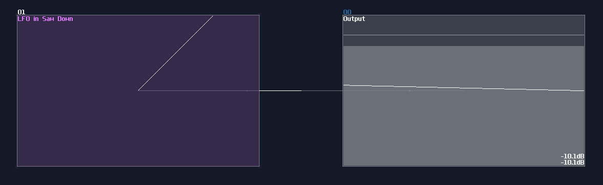
Nevertheless, this line is not useful for drawing since no one would ever drawing anything only from the center with the same slope; thus we need to find a way to define the length of the line and the start and the end point of the line.
To define start and end point, we need two pairs of DC input, and let the four input as: Ax, Ay, Bx, By
Once you have the four amplifiers, you need to filter the signal by channels, which all x input only allows left channel to go through, and vise versa for the y axis.
To find the distance of the line segment, we subtract Bx with Ax, and By with Ay; for example, if Ax = 25, and Bx = -5, the total distance will be -30 (-5-25). With the correct magnitude, we can multiply it with the aforementioned LFO module, to get the line with a correct length and slope.
Although the line is now in the correct orientation, the location is wrong, so we must add the offset from point A to plot the final result:
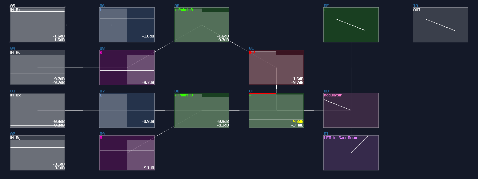
Circles
Don't fooled by its curvature, circle is a simpler object to render than lines, thanks to a flawed LFO shape: The Sine - Cosine Mode.
Originally, this was a bug from a LFO, produced an uneven panning effect owing to the wrong phase offset; however, this bug is an excellent feature for drawing circle; hence, we can simply use sin (0) panning mode for the LFO like shown:
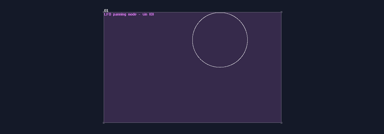
To draw a circle from its center, based on a given radius, you need scale up the circle by a gain of 2, and bring it down by -128DC unit to the center. Once you have "normalized" the circle, you can manipulate the size using constant DC with a modulator like shown:
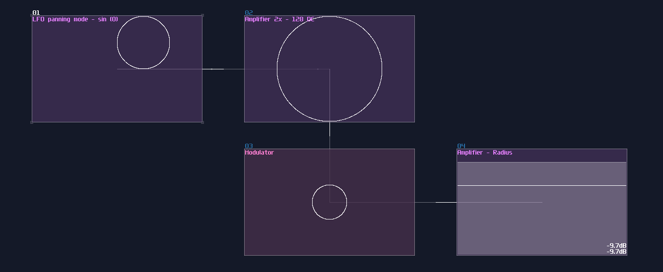
Conclusion
You have now achieved on drawing your first line and circle! For the next chapter, we will expend the concept from circles and line, to make some other shapes.
Example Project:
Arcs, Spirals and Curves
Overview
In this tutorial, I will tell you how to build arcs and spirals based on the knowledge from the previous chapter.
Arc
Sometimes, we only want to have part of an arc of a circle, to form curves, semi-circles or fans. To do that, you need two LFOs, synced with the same frequency, and set the waveform into square and circle respectively. The smoothing function for the square LFO should be off to get a clean cut for the arc. Once the LFOs have been set, multiply both signals using a modulator, and you will get an arc of a semi-circle:
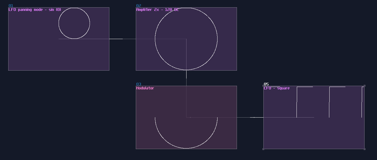
If you change the duty cycle of the square signal, you can get different arc proportions; more the controller goes toward to the minimum, more complete it becomes, and vise versa towards to the maximum. You can change the phase of the square to change the starting point of the arc too, but make sure you have clicked the stop button or using midi signal to reset both of the LFO to have a consistent orientation:
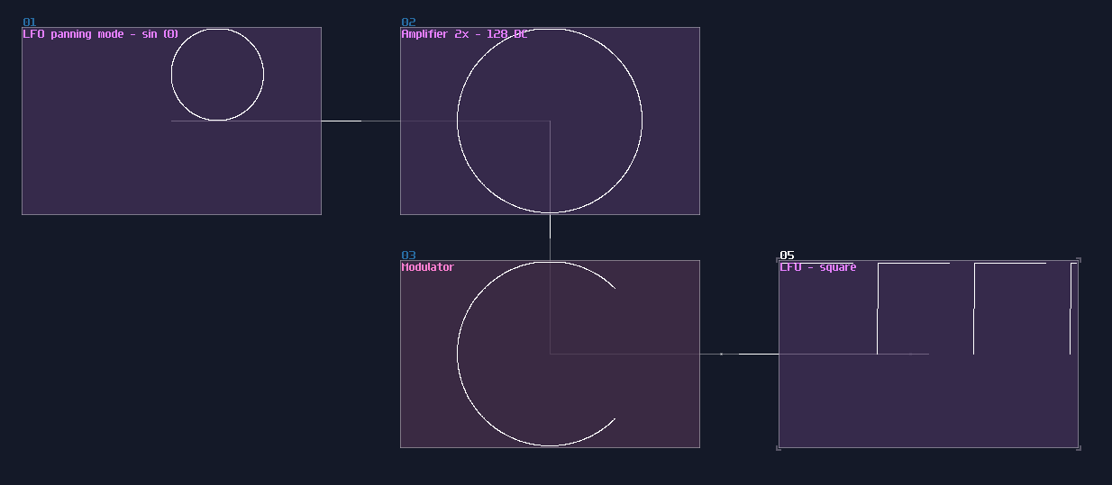
Spiral
There is only one step ahead to convert an arc into a spiral; all you need is to change the square wave LFO into a saw wave:
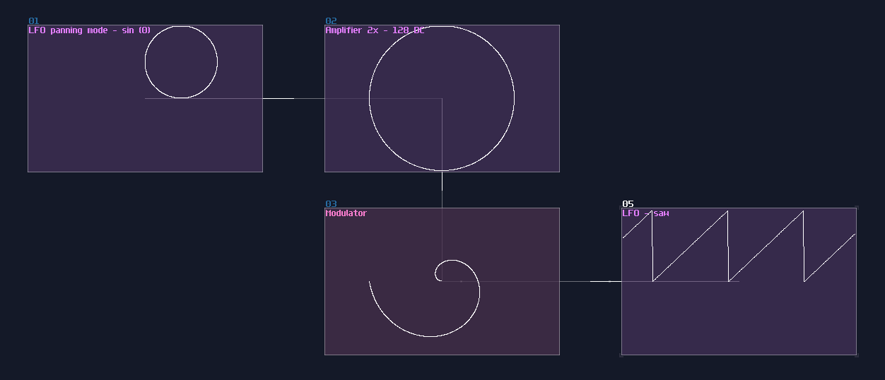
We can get a denser spiral by halving the frequency of the sawtooth by the following equation:
\[ \text{frequency of sin LFO } \div \frac {\text{frequency of sin LFO} }{2^n} \]
In this example, the frequency of saw is 4 times lower than the sine, so the spiral is 4 times more dense than the previous setup:
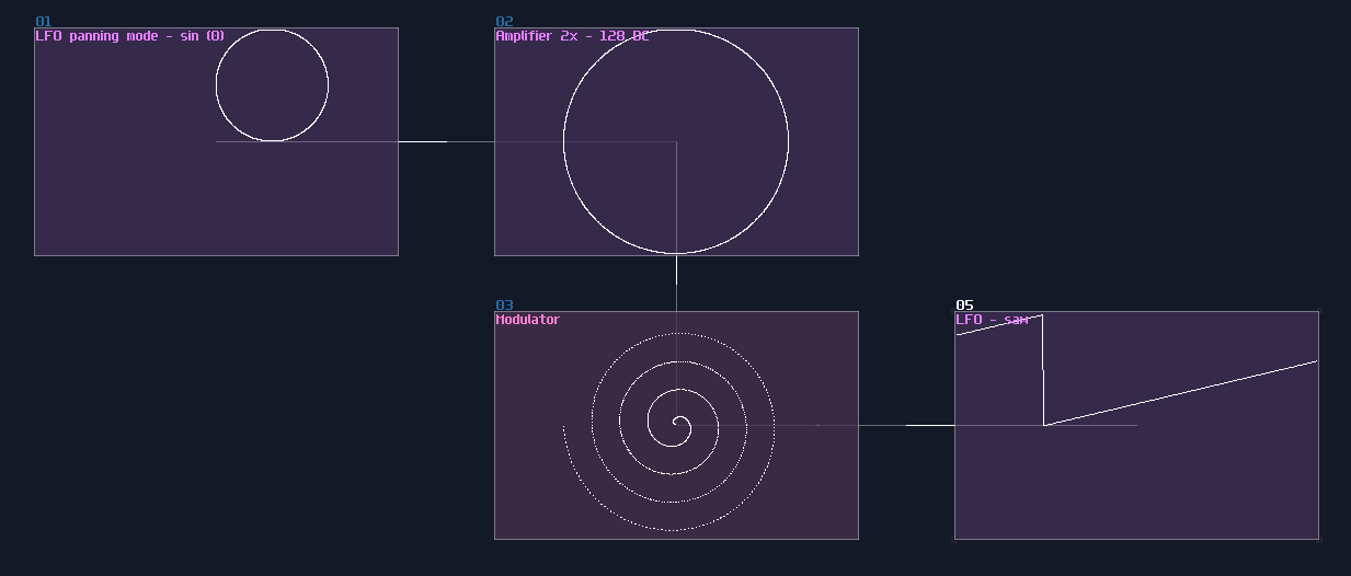
By contrast, if you set the rate of the sawtooth wave by \( x \times n \), despite being less dense, it draws a rotation symmetrical pattern by duplicating the original segment by n times; here is an example for turbine like shape, multiplying the saw frequency by 5:
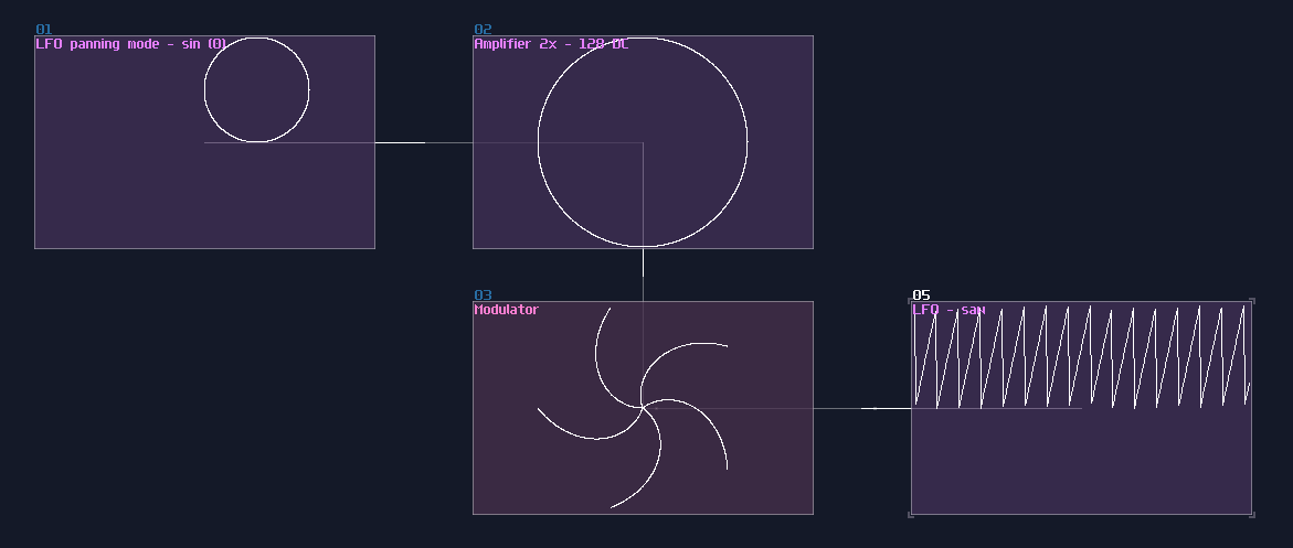
The direction of the spiral is depends on the type of sawtooth; if you want your spiral spinning in counter clockwise, you need to use saw down instead of saw up:
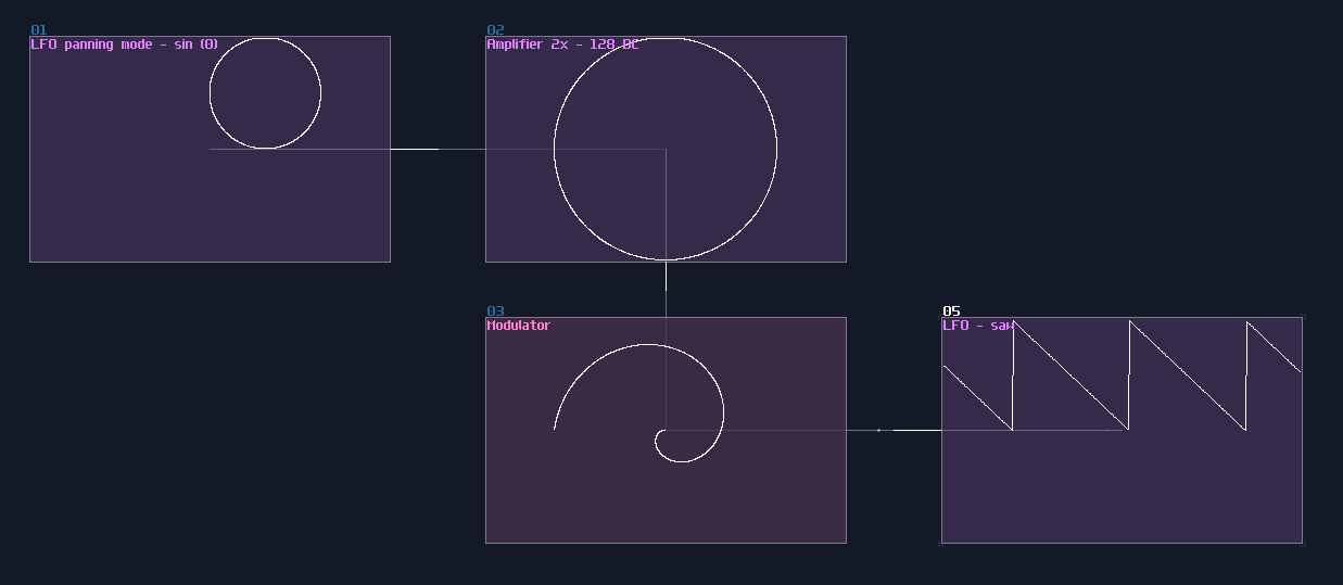
Waveshaper
Waveshaper also comes in handly if you want to draw a wild looking curve, by simply draw a curve in the waveshaper without DC blocker. You may use symmetry setting optionally depending how you want to draw a curves:
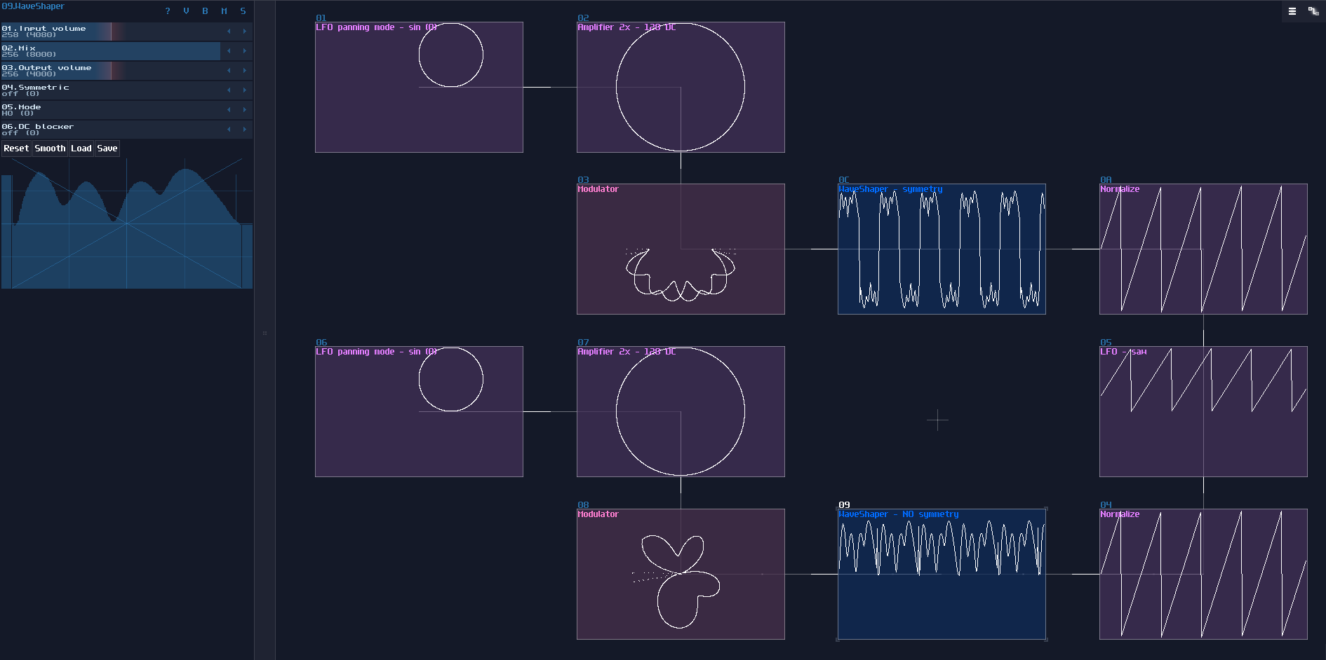
Conclusion
That's about it; as you can see, there are a lot ways to play with curves and to make complex pattens only using LFOs, Amplifiers, Modulators and Waveshapers, go ahead to messing around with different modules, to see if you can get something wilder. For the upcoming chapter, I will add another level of complexity by introduce the terms: Multiplexing
Example Project:
Complex Shapes With Multiplexing
Overview
If you can play it slowly, you can play it quickly.
"If there are only points, line and circles, why are those seven segment displays existed in the pong game and the VOXCOM 1610?"
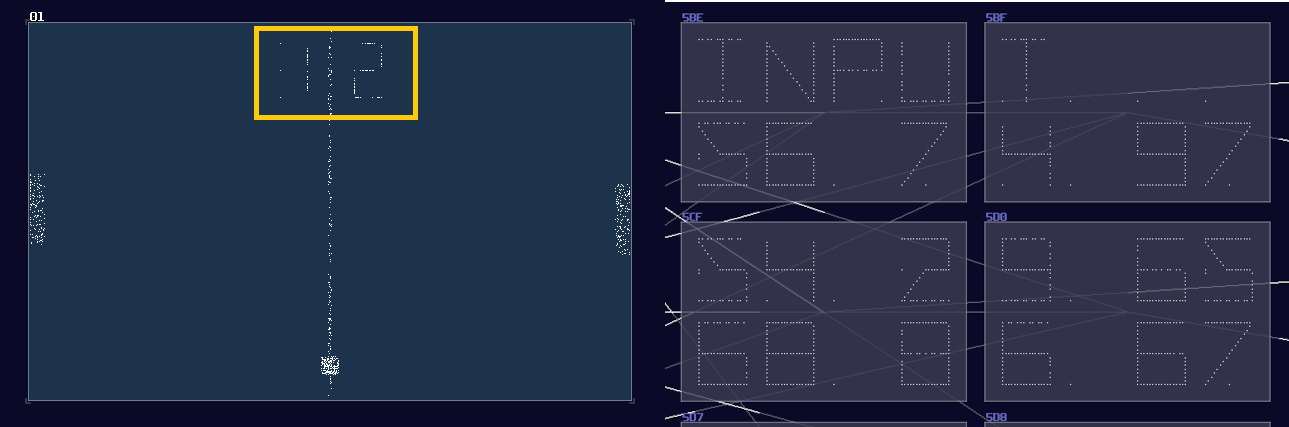
As you are wondering, there is no way to make display using the techniques I have mentioned before because there is no way to conditionally control the individual segments other than redraw everything. To achieve such behavior, you must do Multiplexing.
Concept
Let we put SunVox away for awhile for introducing the concept. In the real world, displays don't have an one to one pin for every pixels because this approach is expensive and space inefficient. Take a standard standard definition 16:9 television as an example 1; if the aforementioned way for controlling pixels was used, you would needed 640 x 480 number of control pins! (307200 in total) There is no way to have that many pins for a processor to control, not to mention how we can suppose to route all the connections with all three colors.
Therefore, to make it more space efficient and easier for processors to control, one of the solutions is to connecting the input pin of LEDs into specific rows, likewise to the output pins into a specific column, forming an matrix like shown2:
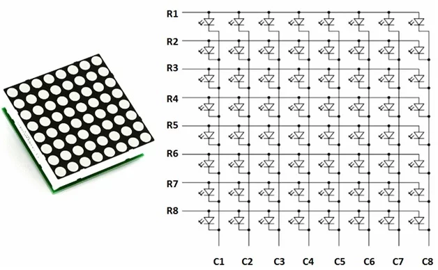
Great, we have now reduced the complexity of connections from \(O(n^2)\) to \(O(2n)\) which is far easier to manage, especially for larger displays. With this approach, we can light up individual LED by switching on the a specific row and column. I have prepared a little simulation so that you can try out the LED matrix:
Nevertheless, there is a problem: the matrix works for individual light, how about a more complex shape, like a letter "A"? No matter how hard you have tried, you can either able to switch on or off for the whole row or column of the matrix, and you can't switch off the middle LEDs.
This is where Multiplexing comes in. Multiplexing doesn't generate the whole image, but one line at a time like shown:
If it can do it slowly, it can do it quickly. Once you have increased the simulation speed, you can start to see the letter "A" on the dot matrix display because it is fast enough to fool our eyes to see it as a single still image rather than a bunch of scan lines although it is slightly dimmer than a constantly on LED.
This is the priciple of multiplexing, so let me show you how to do that in SunVox.
Implementation
Let me start from a simple example, making an interlocking twin circles. Here is an image made by overlapping two modules:
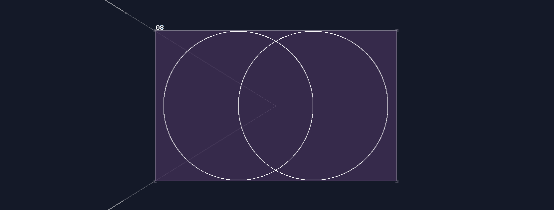
Clearly, we can't do that inside a metamodule because we only have one output channel, so we must combine the two elements into one before returning the result. We can't just sum two images using amplifiers because it will only sum the total magnitude of two circle into one, resulting in a larger circle:
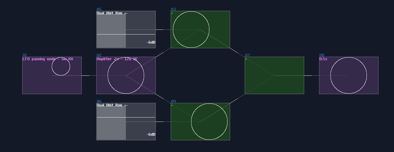
For that problem, we must show them one at the time; this can be done using a square LFO and a NOT gate, alternating the first and the second circle using modulators. Keep in mind that the frequency of the square LFO must not be the multiple of the LFO which generates shapes, or you will get a incomplete shape:
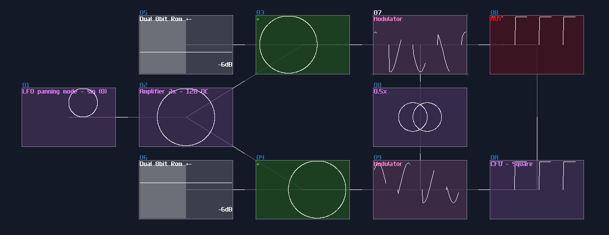
For more segments, I will show you the solution by building a 5 segments diamond:

Since there is more than 2 components, you can't just use a single LFO to separate all the elements, and you will always have overlapped shapes. For this situation, you need additional delay modules and a modification to Duty Cycle of the LFO. To generate a pulse with the correct weighting, you may loosely base on the following equation:
\[ \text{Dyty Cycle } = 256 - \frac {256} {n} \text{ , where n is the number of segments}\]
For the diamond, it is true that you can split the pulse into 5 parts, but because the resolution of the controller, the duty cycle might have some rounding error. Hence, I normally round up the number to the nearest \(2^n\) which is 8; I based on 224 which has a subdivision of 8, but because the LFO is not perfect, and overlapped segment might exists, I picked 226 as a result. For the refresh rate, I used 347Hz which has no harmonic relationship to the generators which is 256Hz.
Now we need to find a way to select the segment sequentially; thus, we need modulator for each segments. The top segments can be connected directly to the square LFO, but for the following segments, we need to control them with a cascaded delay, with the delay time which is exactly the timing the LFO times the number of sub division that is 8 in this example; therefore, we need to use 2776Hz for the delay.
Once you have set and chained the delay, you can now sum all the segments into a single amplifier, to complete the image
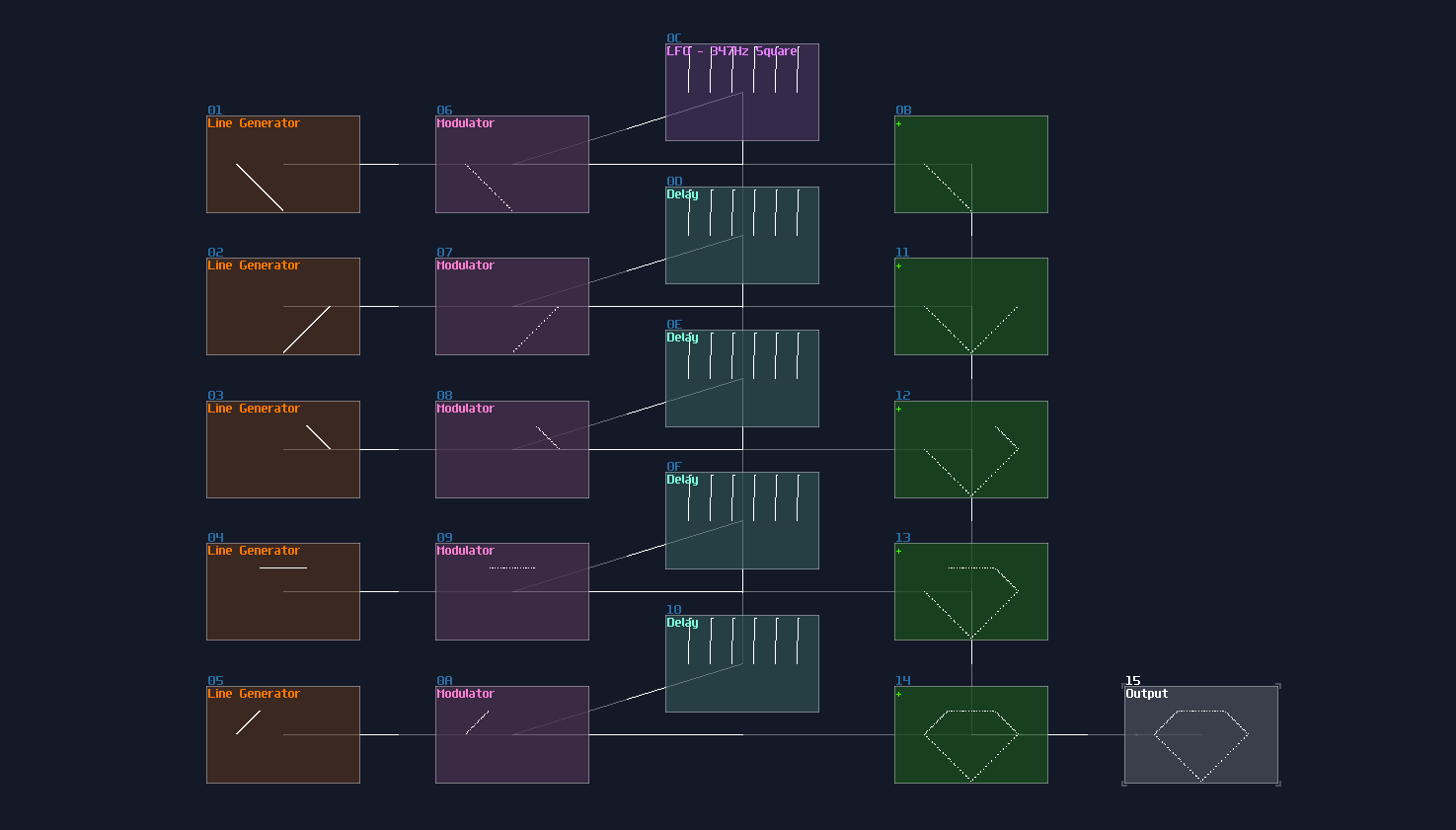
Because now you have controlled the segment independely, you can put an additional Transistors (or Sound2Ctl) before or after the delay chain, to dymanically control each segment, to form a 7 segment display like my pong module:
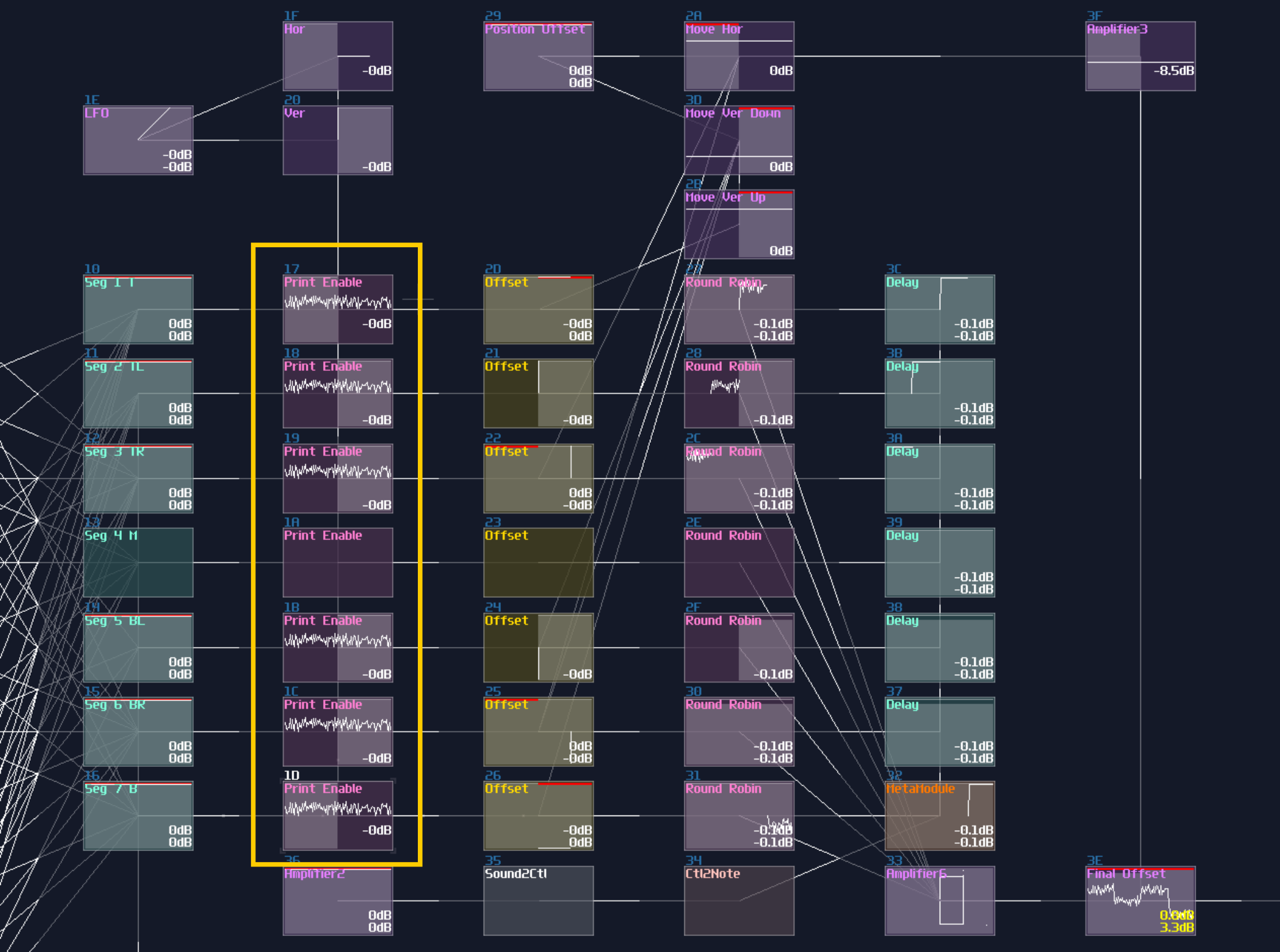
Sometimes, LFO clock is not necessary which you can replace it with a Sampler with a custom, looping waveform. To recognize the first segment of the sample, I have inverted it into the negative side, acting as a pilot signal3, and you may see it at the left side of the waveform which I have used for a 14 segment display as shown:
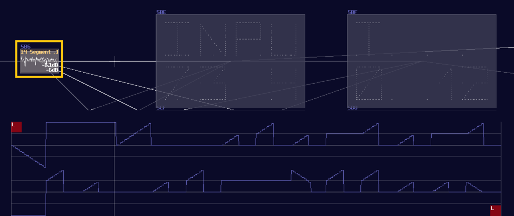
With a pilot signal, you can use that for triggering the first segments by using a negative detector; the detector should generates such a uniform pulse that works like a pulse generator we have made for the previous design; after that, you may use the same delay trick to print the remaining segments, as long as you remember to invert the signal to the correct orientation:
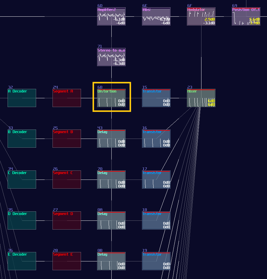
Limitation
Multiplexing is great if you want to build a complex pattern, but it is not a sliver bullet for everything, especifically if you have too many things wanted to be rendered. Hence, I am going to point out a few:
Fainter Images
More the components, more the context switching, if your shapes have too many conponent to be rendered at the same time, the image will be faint to see. To show that limitation, I start by showing from a single pixel:
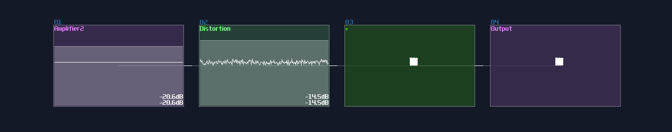
It is nice and clean, but now, let me emulate the multiplexing behavior by quickly switching the position of the pixel using a metamodule containing a DC generator quickly moving by a pattern automation, like shown:
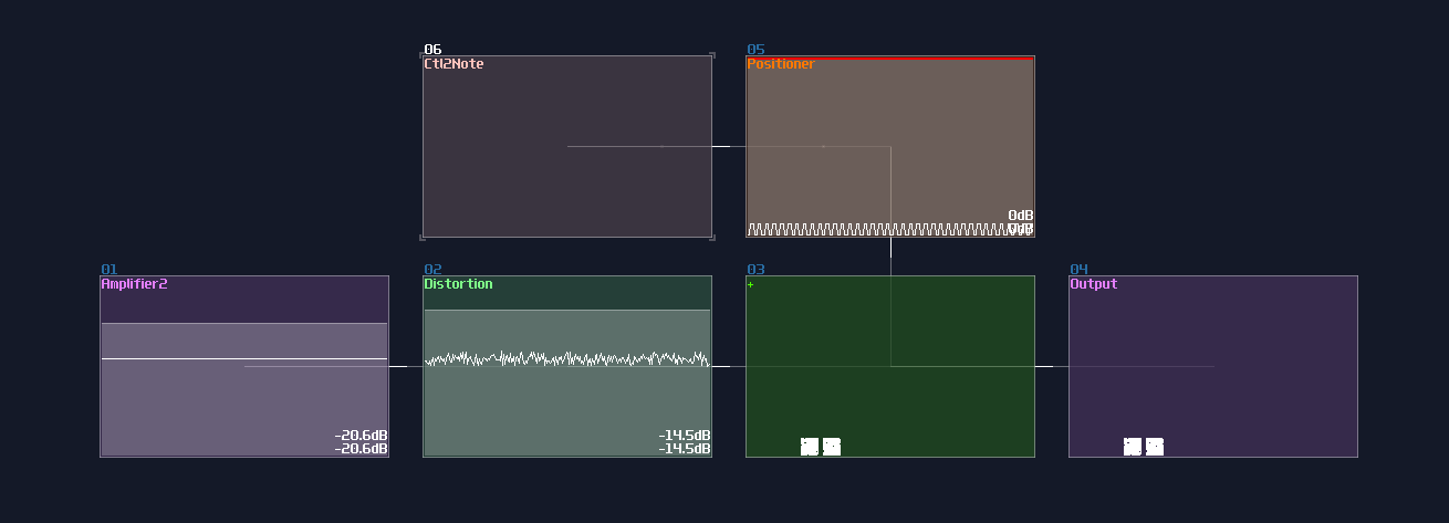
It is currently displaying two pixels, meaning the two segment only have half of the time on the screen. Let me graduately add new segments by a multiple of four, and see what would be happened if there are high number of pixels:
4 pixels:
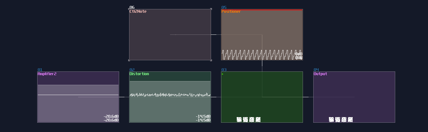
16 pixels:
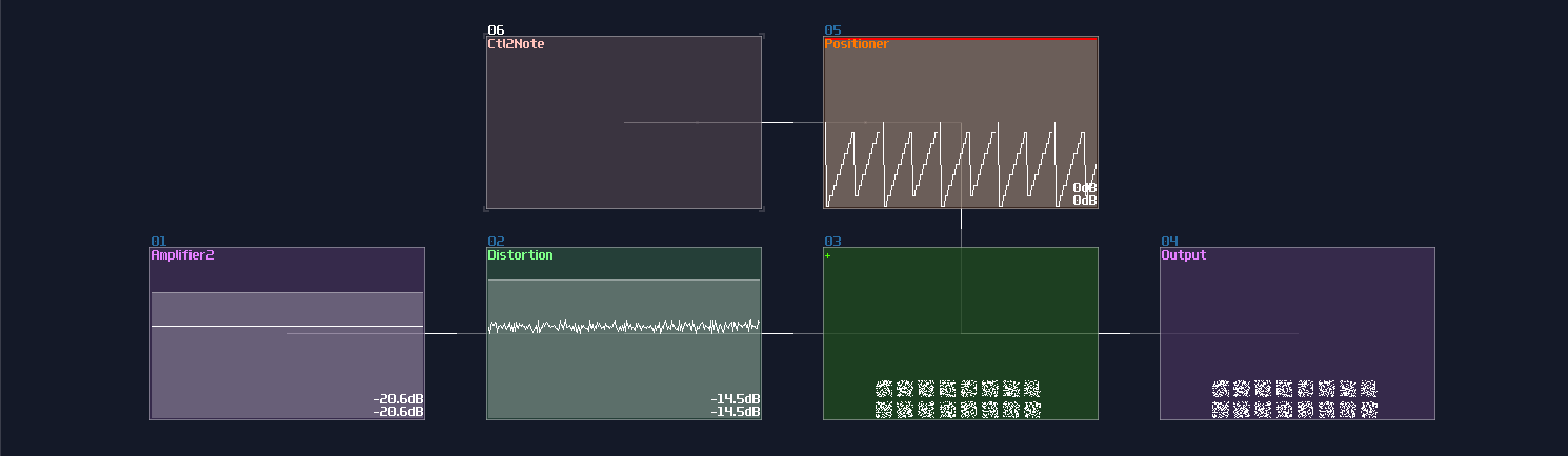
64 pixels:
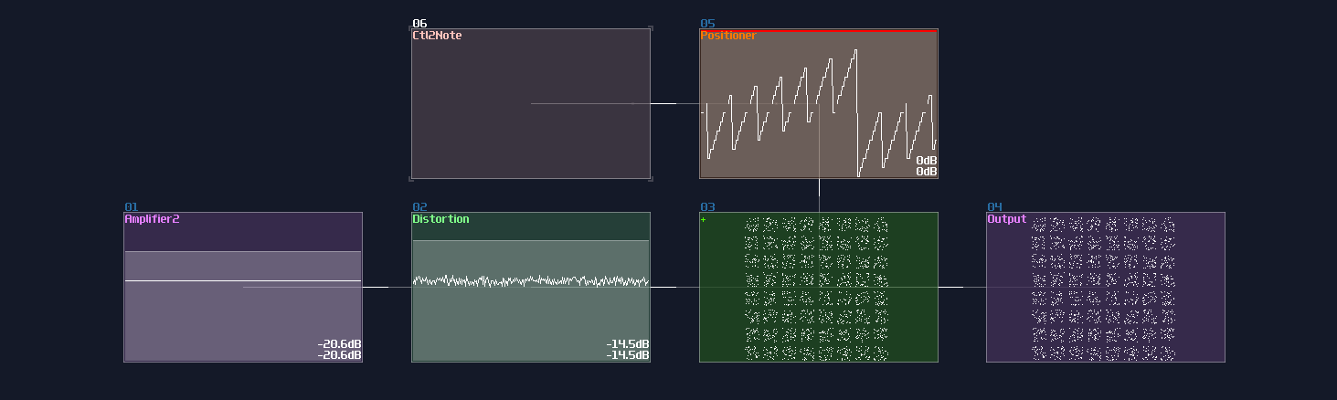
At the 64 pixels matrix, they are much harder to see and the square are much less crisp since each square only share 1/64 of the rendering time, causing less point plotted with the same oscilloscope buffer. This currently have no single output module solution because it is bound by the buffing time of the module visualizer, unless there is an update that multiple output is possible while the visualizer will output all the point from the multiple output channels simultaneously.
Imcomplete Imgaes due to Synchronization
Another limitation is that every segments of the same level must have no harmonic ratio to another. Take the diamond as an example; if you set the frequency of the line generators same as the multiplexing pulse generator, you will get an imcomplete image by taking the same segment of the lines:
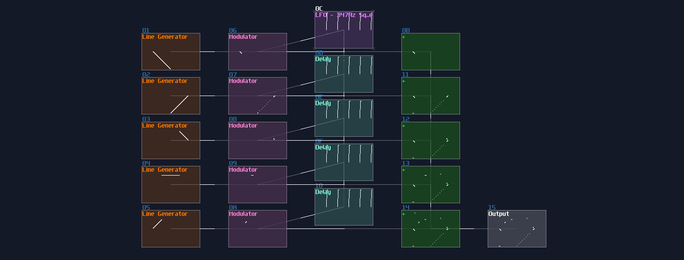
This can be problematic since you may need to find the sweet spot for each generators by trial and error.
Conclusion
What a journary! We have finally made it to the end of this chapter about doing multiplexing for drawing a more complex shape; for the following chapter, we are going to mess around with the geometric transfomrations.
Example Project:
Reference
Geometric Transformations
Overview
To make your drawing animate, you need to know about the 4 basic geometric transformations, and I am about to tell you that, starting from the most trivial solutions.
Translation (Moving Things Around)
Moving things are as simple as addition because you only need to add an additional DC offset to your original elements, where the axis is controlled by the respective channels:
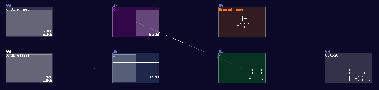
Reflection (Mirroring Things)
Reflection is as simple as translation because instead of adding an offset to the respective channel, you only need to negate of the channels. In this example, I mirrored the text Logickin by inverting the left channel:
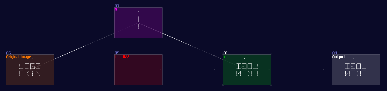
Dilation (Scaling Things)
Not surprisingly, If amplifier is for addition, modulator is used for scaling an image because dilation is basically a multiplication. In fact, increasing and decreasing the gain of any modules can also do the same trick.
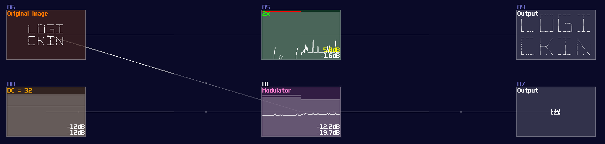
Rotation
"Yay! The solutions above are very simple! It applies to rotation, right?"
Sadly, this is the tricky part because there is no trivial solution; however, with a bit of math and the understanding of trigonometric concepts, you can relatively easily to get it spin. Let me show you the rotation equation1:
\[ R = \begin{bmatrix} \cos{θ}&-\sin{θ} \\ \sin{θ}&\cos{θ} \end{bmatrix} \cdot \begin{bmatrix} x \\ y \end{bmatrix} \]
For people who don't understand matrix, let me convert that into two separated equation so that it is easier for you to follow:
\[ x^\prime = x \times \cos{θ} - y \times \sin{θ} \\ y^\prime = x \times \sin{θ} + y \times \cos{θ} \]
Where θ is the number of degree of your rotation.
After we have simplified the equation, we can now implement it into SunVox because not only everything is straight forward, but we also have learnt how we do trigonometric function. To do the multiplication, we can count how many times we have used the sin and cos function, which is four in total; because all of the trigonometric functions share with the same θ as variable, we can further reduce the number the trigonometric modules. As a result, you only need one "sin" module connecting into two modulator for multiplication, likewise for the "cos" modules.
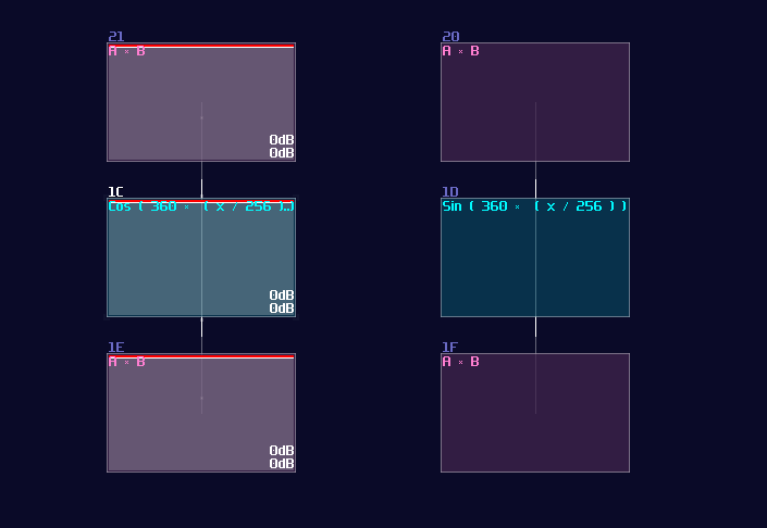
Once you have set the multiplication right, you may sort out the remaining part. Since the result of x requires a subtraction, we must invert one of the product of sin θ, and combine with an output of the cos θ, similarly for the other group without the inversion. For the input, input y connects to the modulator that connects with the cos module, and connects to modulator from the sin part that contains an inversion, while input x connects to the remaining modulators.
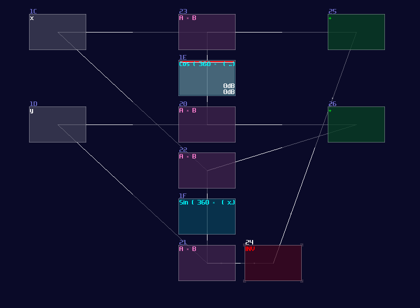
To drive the structure, you need to feed your original image, separated into x and y according to the channels, and feed the angular information into the two trigonometric modules. Because of how DC offset works, degree doesn't exist in SunVox, so you should base on the following equation to get the correct rotation:
\[ \text{DC offset} = \frac {32} {45} \times θ \text{, Negate the result for clockwise rotation} \]
For example, if you want to rotate an image clockwise by 45°, you should send -32, according to the equation:
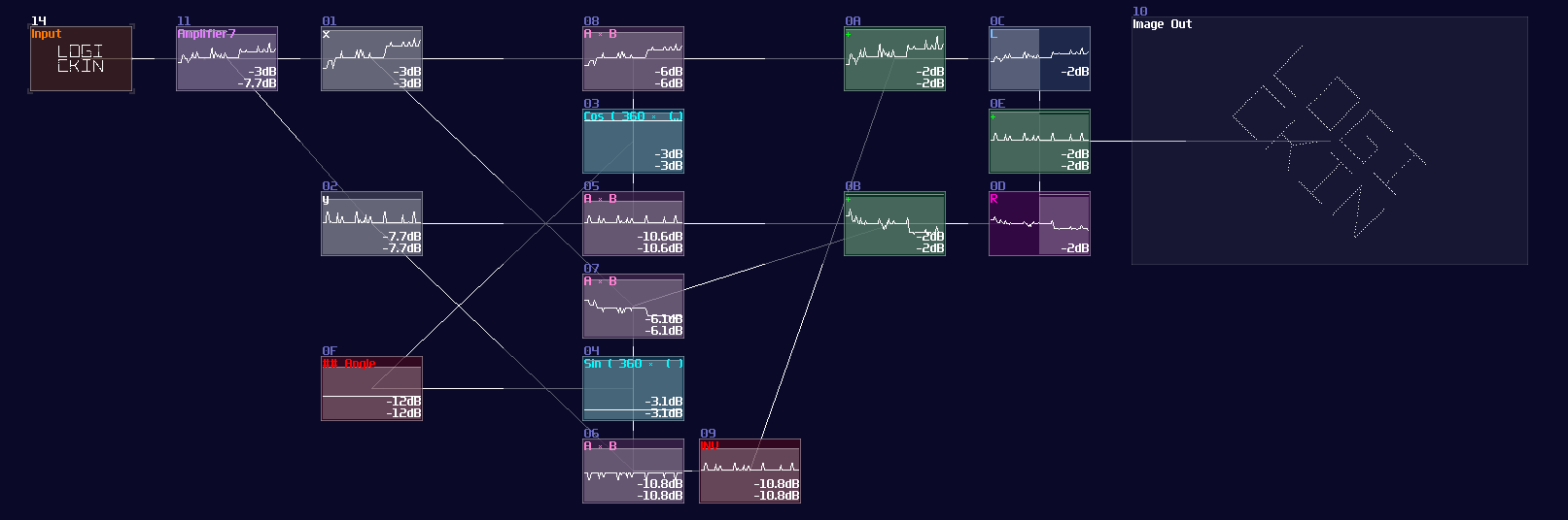
Keep in mind that this structure only works between -180° and 180°. For wider angle, you must warp the DC signal once it have exceeded ±180°. (e.g.: -270 = 90)
Conclusion
Here we go! We have more an less complete knowledge for graphics in SunVox, so let me show you some examples for the following chapters, to put the theories into practice.
Example Project:
Reference
Fun Fact: This was where I had stuck for the original logbook because it was really hard to update the tutorial since then, and I gave up and re-write everything on the mdbook. Hence, this was my last chapter for the original editions, filling with great amount of errors that is tedious to change.
Example - DVD Screensaver
Overview
After we have learnt all the tricks for graphic, we are about to use the knowledge to build our first complex project, the DVD Screensaver!
* Demonstration purpose, this is not the exact version in the following tutorial.
The Segments
DVD logo can be broken down in several elements:
- Two "D"s made of a semi-oval
- "V" made of two diagonal lines
- Two ovals for disk
Let's focus one the easies, the two ovals. This can be done using the same circle LFO, with scaling down the y axis by 0.375 (96 / 256):
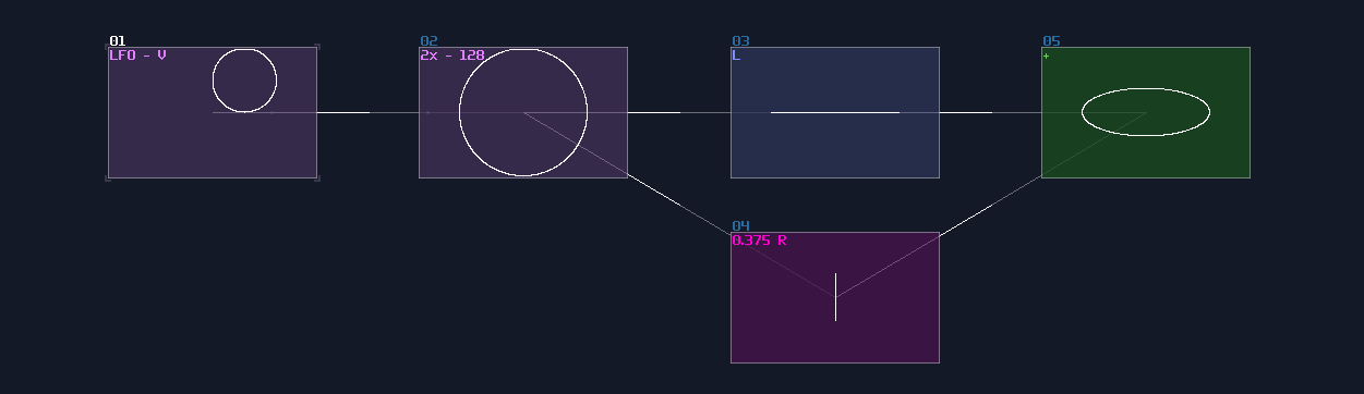
Then, apply a square LFO for multiplexing, where one of the oval have the 0.375 of the original oval:
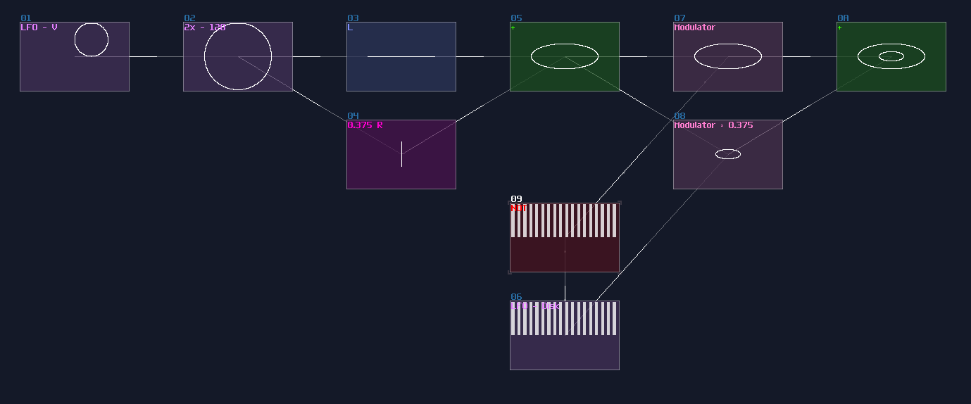
The "V" is also simple; you just need a single Line LFO generator with normalizing to ±128 using an amplifier, and set the y axis with Absolute mode to flip the negative side up. The "V" is a bit wide, so you may decrease the volume of x axis:
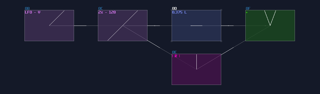
For "D", instead of using LFO, you may use the similar absolute trick to flip the left side of the arc to the right. After that, all you need is a line, combining with the arc using multiplexing. The straight line can be made using the Right channel of the circle, representing as the y axis, so you can save yourself a LFO for line:
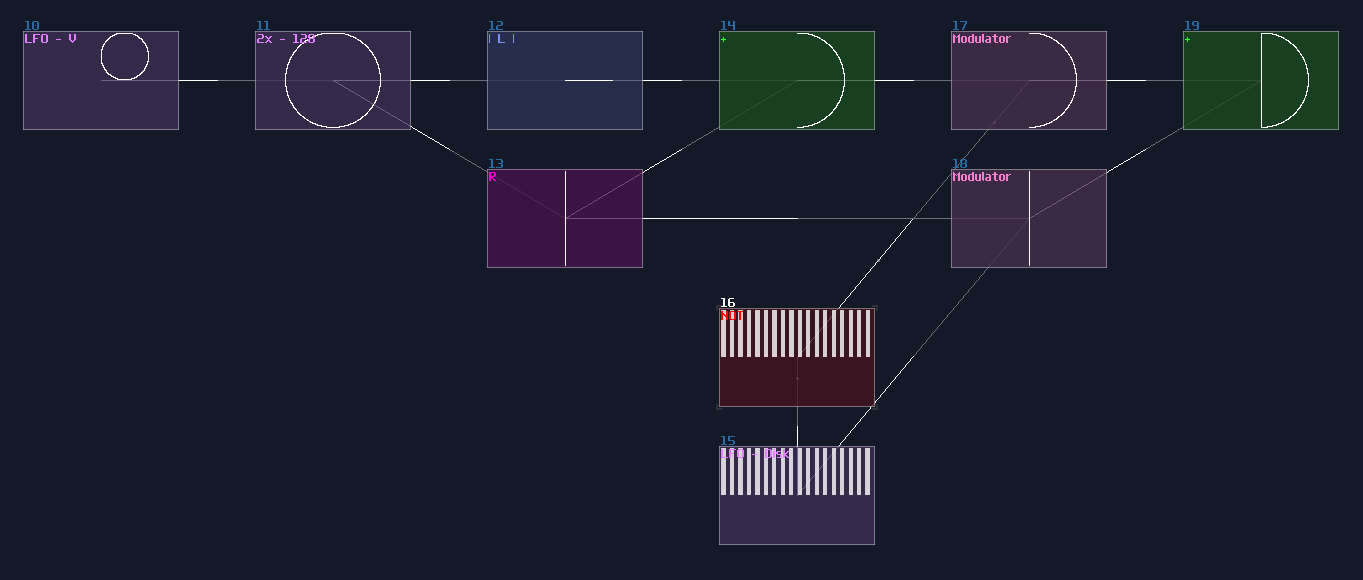
It is the time for merging everything; as usual, they are all multiplexing. Because all of the character are in the wrong position, you must do translation for all elements so that you can get the logo of the word "DVD" on the disk. Due to the compactness, I made metamodules for generating DC offset independently to the Left and Right channel, and the numbers represent the DC offset of Left and Right channels:
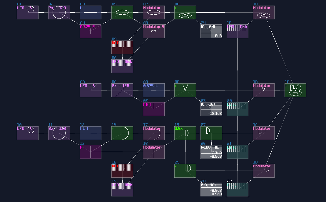
We now have a DVD logo, but... without the iconic bouncing motion, it definitely lacks something; therefore, we can add two more triangular LFO with slow but independent speed, to make it move around; meanwhile, the logo is a bit too large, so we also need to scale it down a little:
Once you have done, wrap it as a metamodule and you are good to go.
Conclusion
You have now understand how to build a DVD screensaver with the knowledge you have gain from the previous chapter; for the next chapter, let me take that into the next level.
Example Project:
Three-Phase Dream
Overview
This is the extension of the previous chapter and they might contains some trial and error which can be tricky at times. Although I have tried my best to describe what is happened, this chapter is a bit confusing due to its complexity. This chapter might have multiple reworks in future.
FULL BRIDGE RECTIFIER!!!
In the tutorial, I am going to make the iconic three phase dream animation using SunVox, by Electroboom.
Idea
Let's see this animation:
Obviously, it is impossible for SunVox to plot the whole image of Mehdi, but we can draw a stick figure, along with his greatest feature, the EYEBROWS!
Drawing Mehdi, Kind of...
We are going to draw a stick figure like so:

We can start by building the head, which is the easiest part. The head is an oval, so we can use the same trick for the DVD screensaver; for the eyebrows, we can also use the absolute function in amplifier, but with a twist which is the Bipolar DC offset, flattening the middle part of the "V" shape. You can do translation using LFO and you can draw the eyes using the vertical straight line generated by the LFO from the eyebrow, likewise for the mouth which is based on the horizontal line:
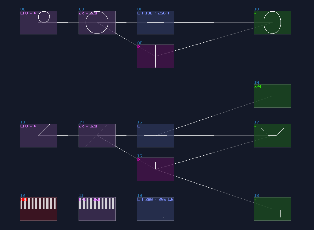
For the torso, we can just use lines from the eyebrow, and the vertical line from the head, with a bit of absolute trick:
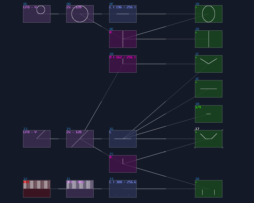
It is multiplexing time! Combine all the shape to form a head and torso like shown, with a bit of translation and scaling:
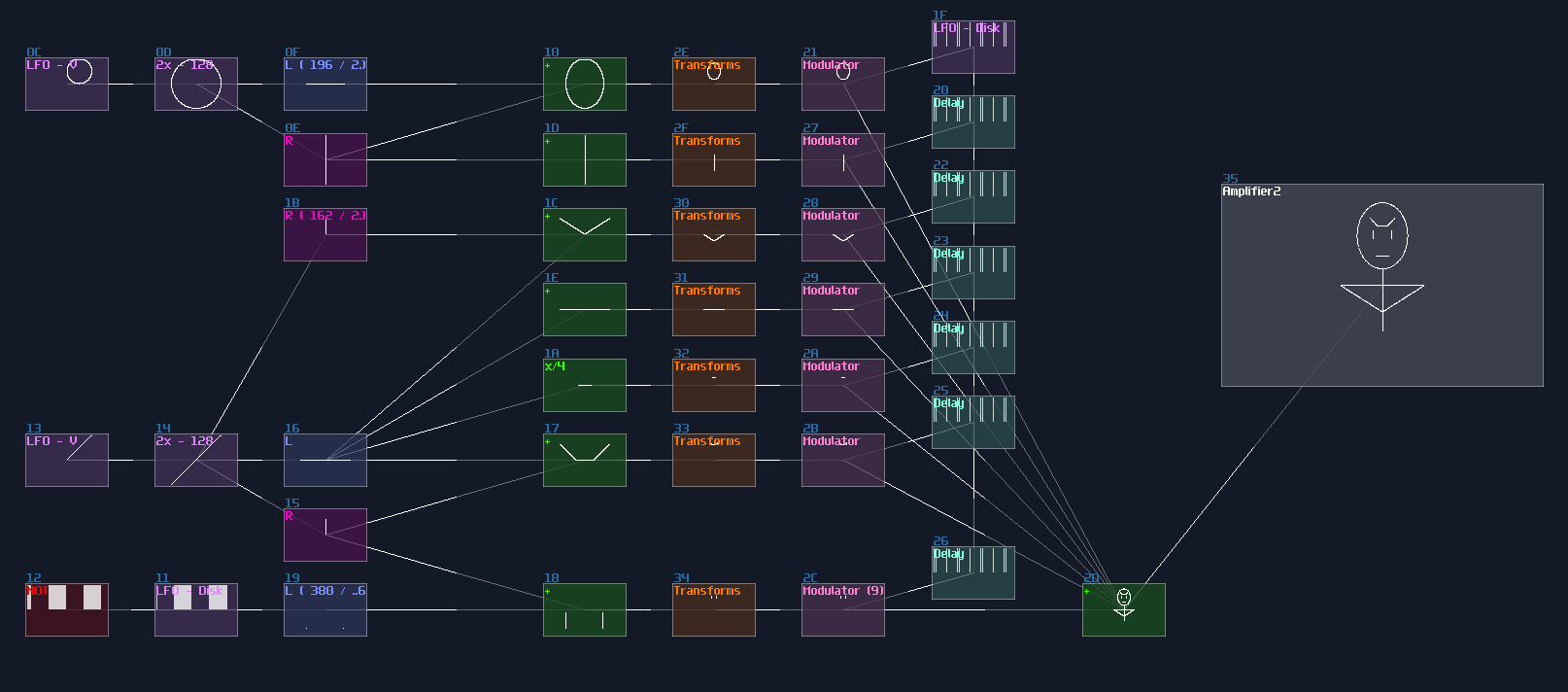
Here comes the hard part. We want Mehdi to move up and down, with his knees expanding and contracting, and we need four lines for that:
- line for the thigh
- line for the leg
- mirror version of them
Thus, we need to draw lines given two points, with multiplexing; there is also an master LFO, clocked at 1Hz, to sync all the movement and the later spinning motion. Unfortunately, this part requires a bit of trial an error, so you may need to mess around with the gain of L or R separation. The way to plot three points are the following:
- The constant point as foot standing on the ground
- The knee, that move outward and inward, quarter magnitude of the original master Sine LFO, with opposite phase. It requires a bit of downward motion as well; after halving the LFO sine, you need to apply and additional volume change into 141 / 256 with another amplifier.
- For the hip, you only need downward motion which comes from the halved master sine LFO.
- The halved master sine LFO also controls the torso.
- Because of having three points, you need multiplexing for the hip and the foot joins to plot two lines at once.
- Once you have lines for the squatting action, make a copy using another set of multiplexing with mirroring.
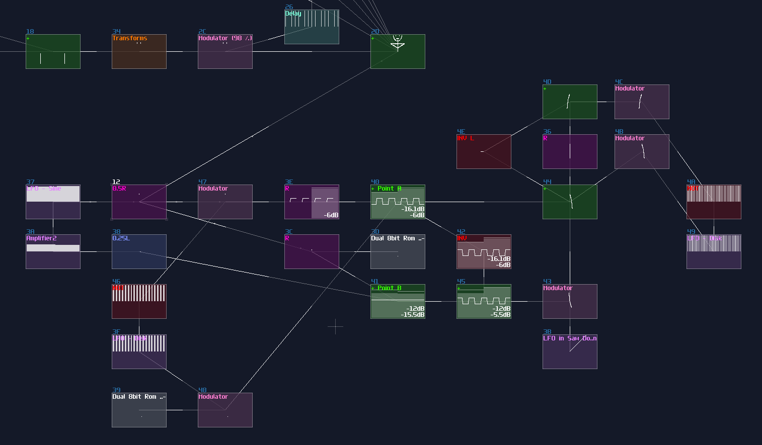
Combine with a 120° arc, we need to do multiplexing again, to form one-third of an image:
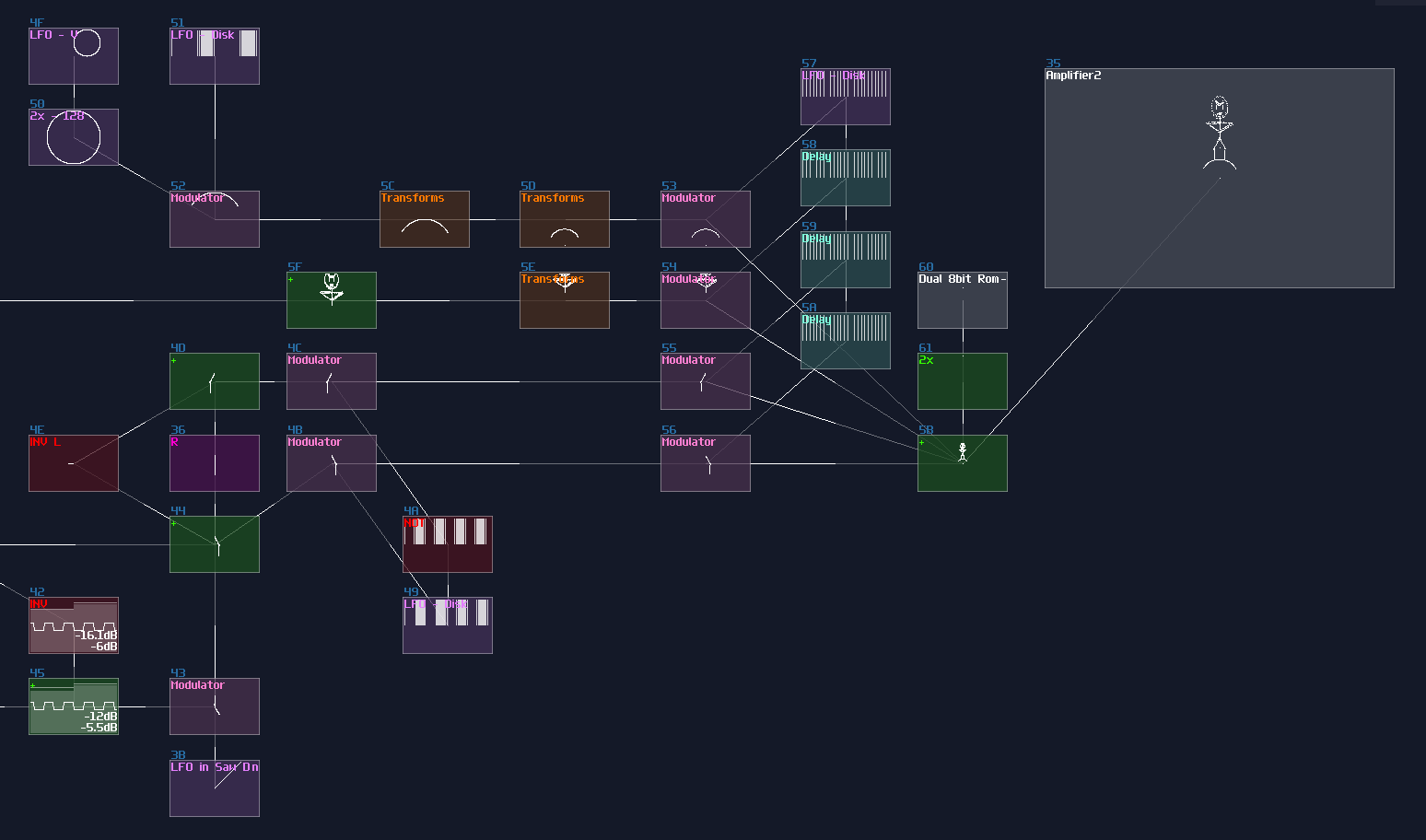
Now, we need to sort out the beam for the crank of the rotor, which is based on the similar concept, drawing a line given two points where the starting point is at the bottom of the triangle, ended with the circular motion, which will be resembled as a crank. The circular motion can be done with a LFO in sin(0) mode, with the same frequency of the master LFO. Multiplexing is also used here, but because Mehdi is more complex than a single line, we may set the the duty cycle more bias toward to Mehdi for a clearer image:
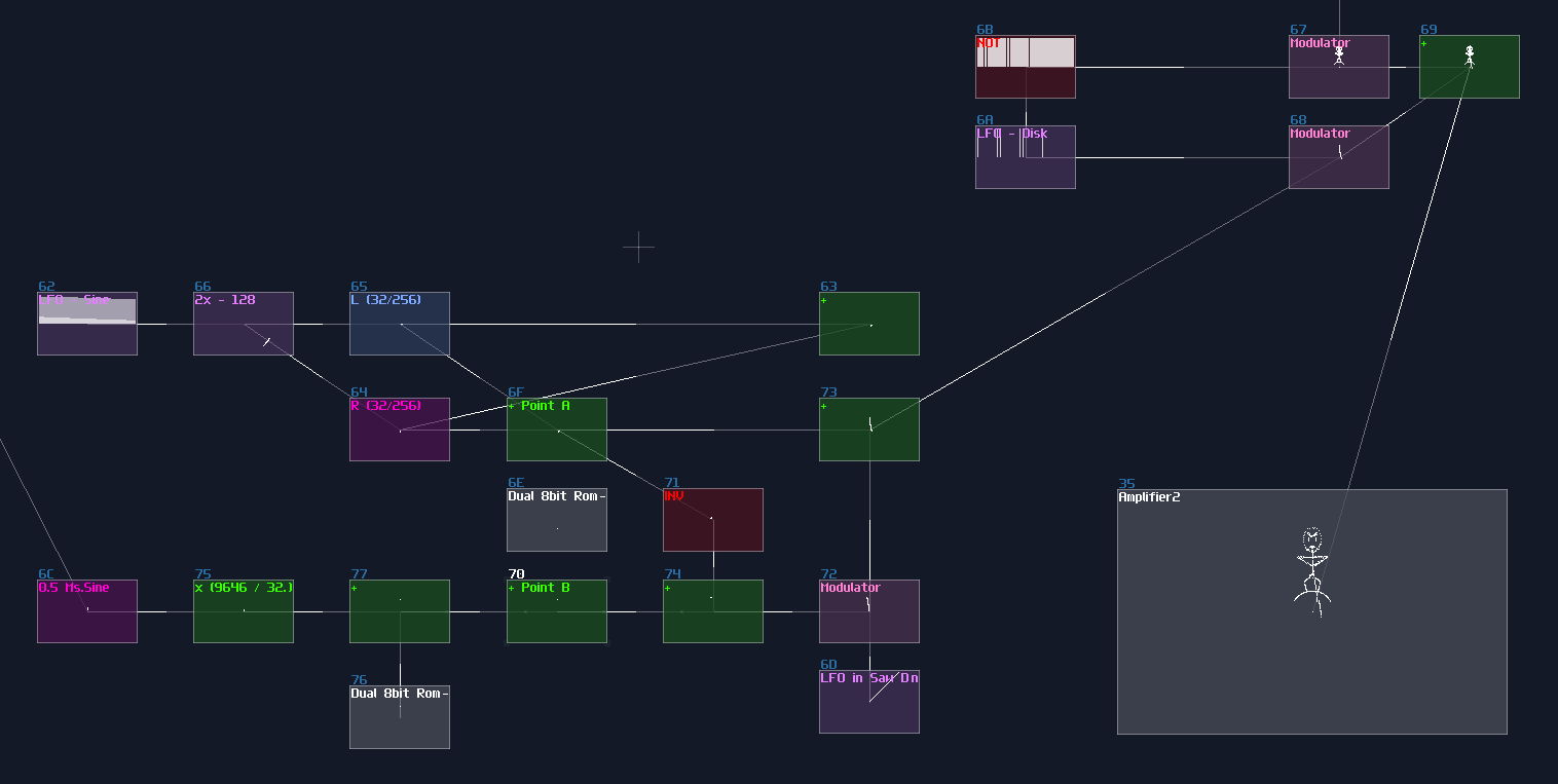
From One Phase to Three Phases
We need two more Mehdis to complete the cycle. Split the same copies three times ±with 120° (±85DC unit) rotation; in addition, if you want all Mehdis pulling and pushing the same crank of the rotor, we need to delay the two copies by 333ms and 667ms respectively which adds an extra period of 1/3 and 2/3 from the 1000ms master clock.
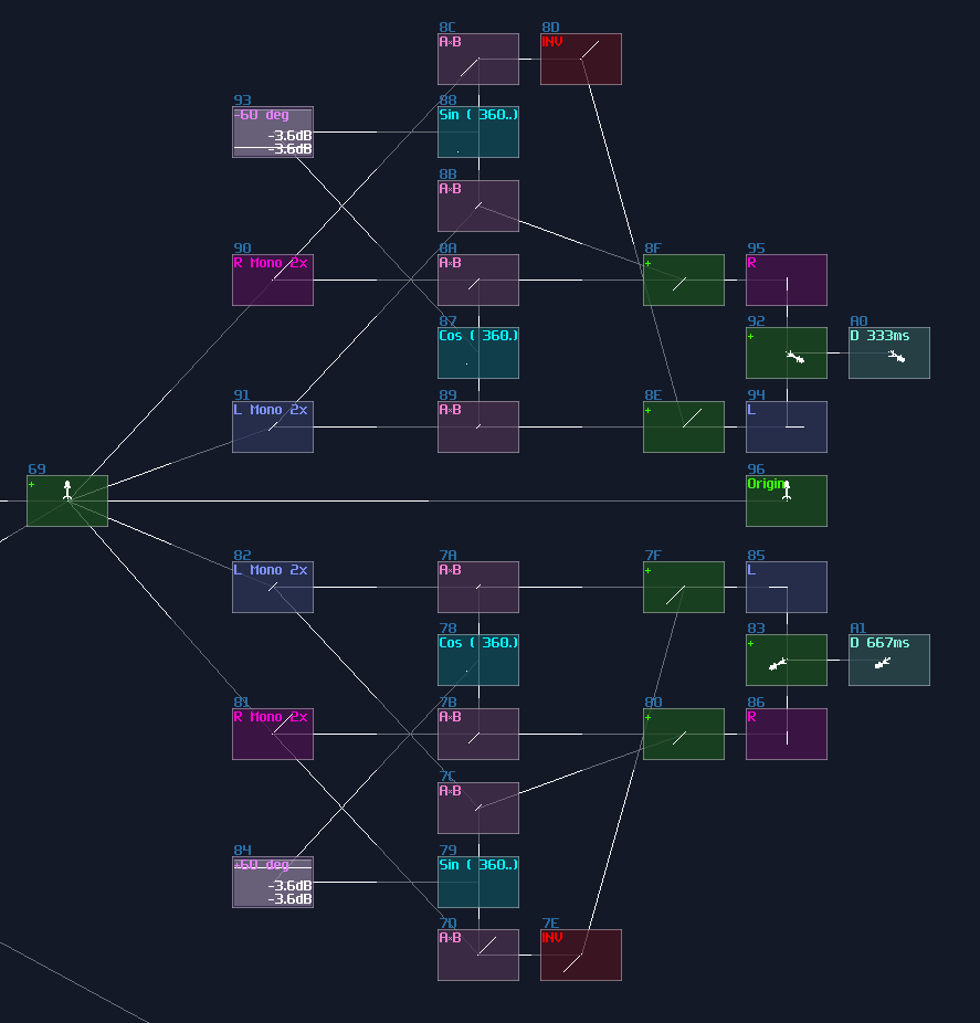
The Rotor
Mehdis are done, and we are now moving on to the rotor. Remember the little unused "+" module when you were doing the circular motion?
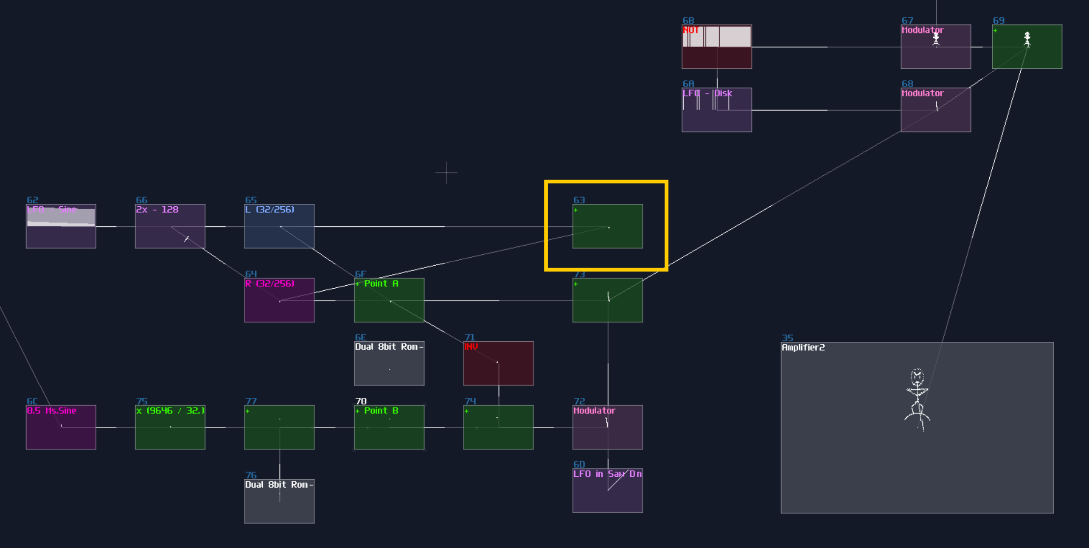
We need that for plotting the crank by drawing a circle.
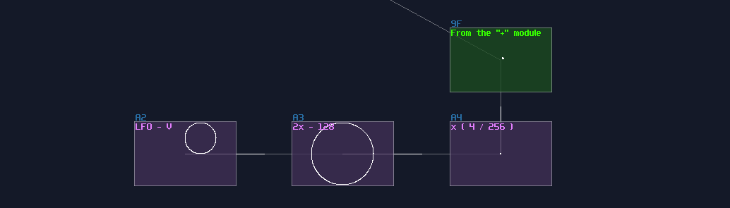
For the rotor, we can do it with a hacky way; using a normalized triangular LFO with a stereo delay, you can print a rectangle due to the phase difference between the Left and Right channel.
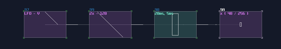
To make it spin, we need rotation, but unlike the previous method that requires sin and cos function, we can squarely use the LFO from the sine generator for the rotation as they are effectively sine and cosine curve so that not only the structure is more simple, but also it is easier to doing synchronization:
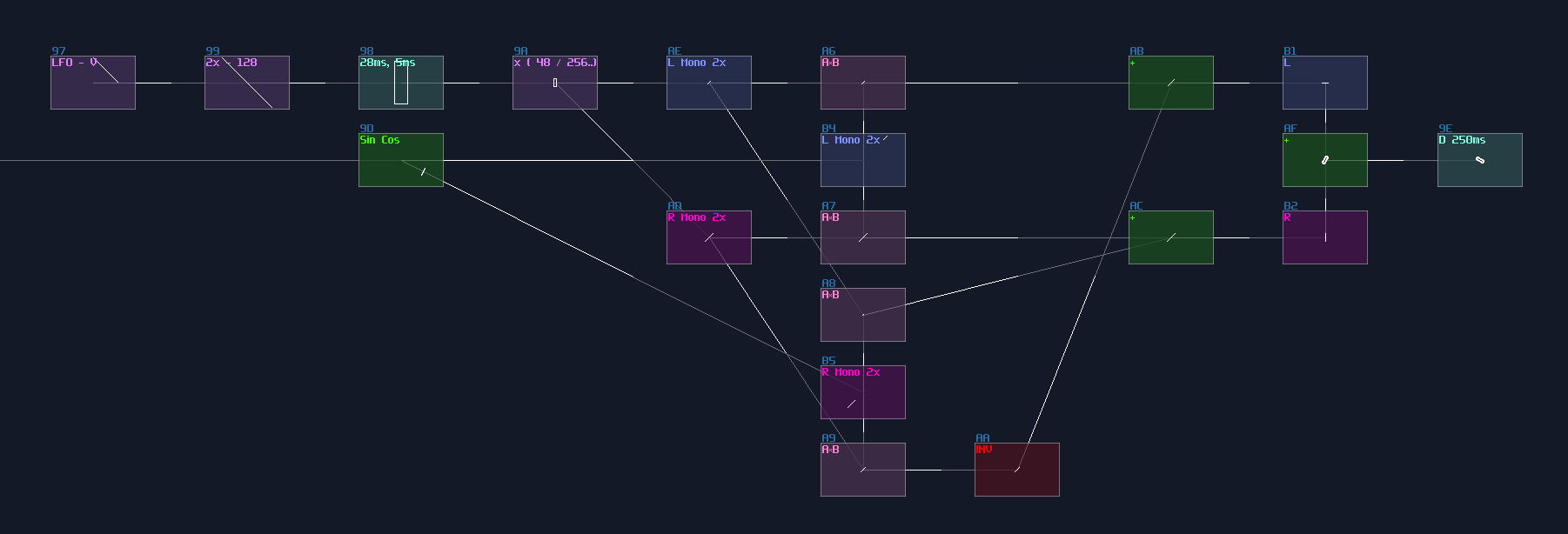
Then we can do multiplexing again to complete the whole rotor:
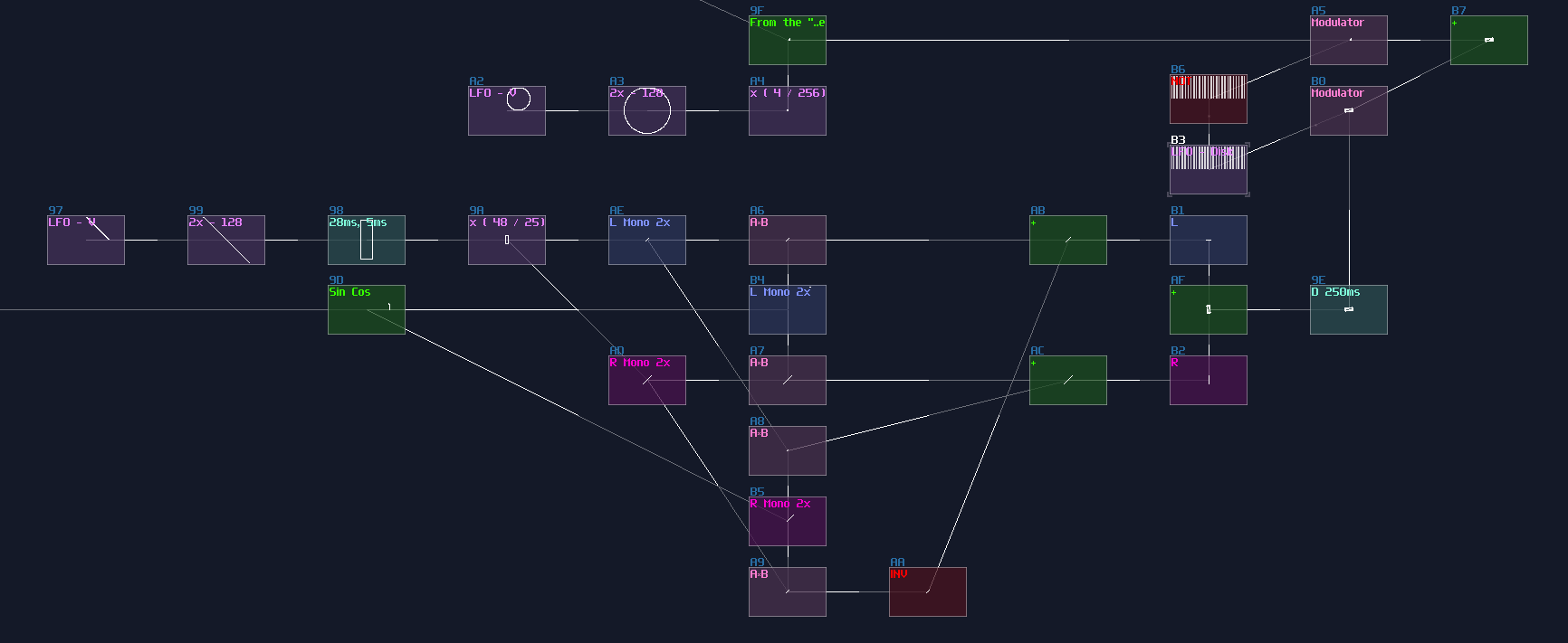
Putting Altogether and Give It a Spin
We can now combine the Mehdis and the rotor into a complete; since Mehdis are much more complicated than the rotor, we need more time for rendering Mehdis. owing to the weighting, it can be quite complex if you use the LFO - Delays method, so let we use a decoder based multiplexer:
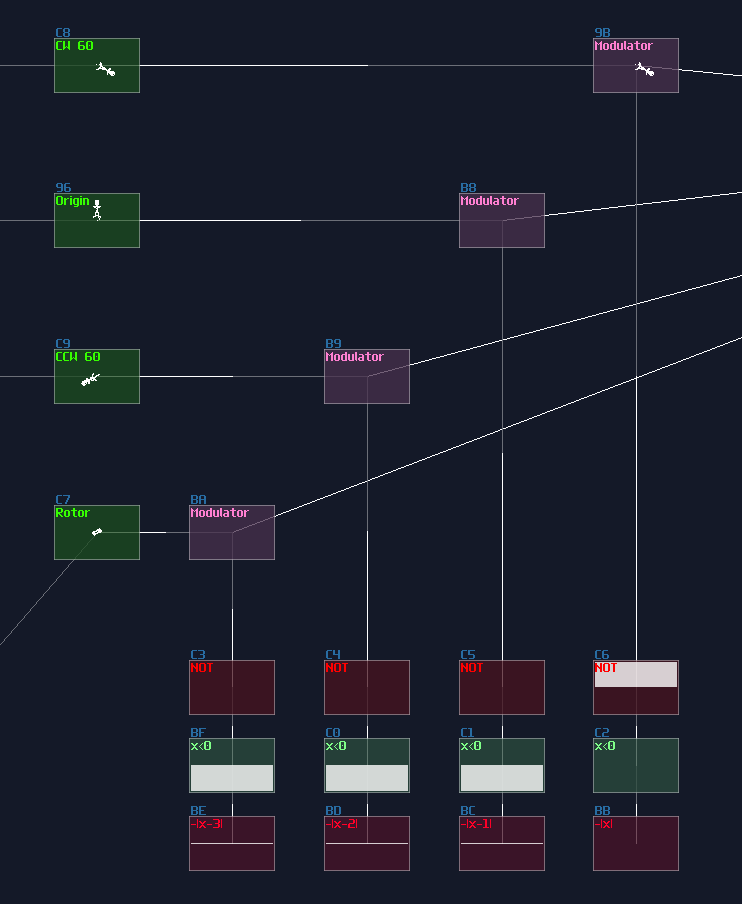
To drive the multiplexer, we need a counter to generate a specific DC magnitude withing a precise time with weighting, so metamodule can be used. Inside the metamodule, you only need an amplifier, with the following pattern:
Controls the DC offset of the amp inside the metamodule, with weighting
0: ----0103004000
1: ----0103004080
2: ----0103004100
3: ----0103004000
4: ----0103004080
5: ----0103004100
6: ----0103004000
7: ----0103004080
8: ----0103004100
9: ----0103004000
A: ----0103004080
B: ----0103004100
C: ----0103004480
As you can see, the Mehdi has three time more screen time than the rotor, to ensure that the Mehdis will be printed cleanly. After that, we can connect the counter to the multiplexer, with Ctl2Note and Sound2Ctl to switch on the module automatically.
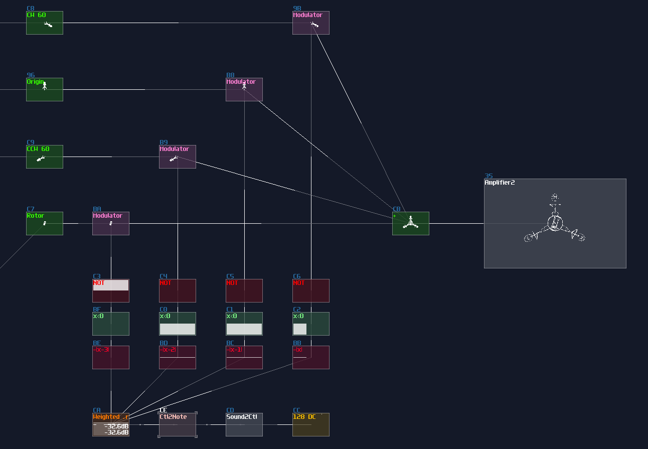
We are really close to the finish line, as we have reached the final step; to give it a gentle spin, you can use the similar trick for the rotor, but a much slower speed:
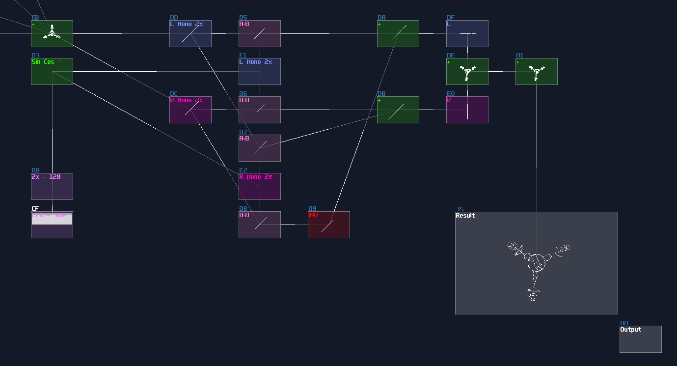
Result
You have completed the animation! Although it is far from ideal, compared to the original, this is what SunVox can do at best, with single module output.
Conclusion
Alright, we have pushed the limit of the SunVox Oscilloscope to draw the three phase dream animations, applied all the techniques we have learnt. For the next section, let me discuss some thought process on building something complex
Example Project:
Checkpoint C
Finally, the is such a milestone because not only you have now understood how to make simple shapes, using multiplexing and geometric transforms, but also I have finally break through the struggle on writing this sections due to the problem of wordpress. Let us have some fun on making other patterns or logos before moving on to the upcoming section!
3xLog Tool kit C - Graphic Generators and Transformation Functions:
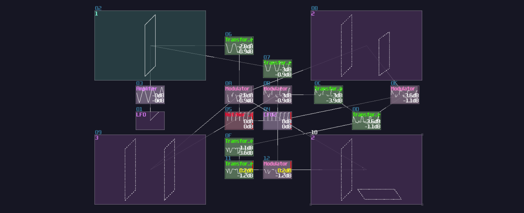 Losing in mind on the graphic stuff? No worries! I have provided a handful of graphic modules so that you can generate basic shape out of the box! You may encounter symbols like "n>" and ">n" for some of the modules because these modules have special input and output signal due to the use of Nyquist Clock Serialization. All you need to do is to connect the modules with "n>" to ">n" to properly render the elements.
Coming Soon
Integration
This chapter is a bit special because there is no new component, but I wanna give some ideas of how to plan your SunVox project or giving some useful tools for building or analyzing your logical structure or modules.
Planning Ahead
Overview
I didn't create VOXCOM out of thin air, and it took a lot of planning before putting the first module. I used a couple of tools to record my ideas and design ISA or computer structure. In this chapter, I will point out some of the good tools for drafting your logical circuit.
Notebooks
Sometimes, the best way to record is actually draw them down on paper because that is the fastest way to note down your diagrams or sketches. I always have some notebook nearby so that I can quickly draw down any idea without losing them due to waiting for loading website for drawing diagrams.
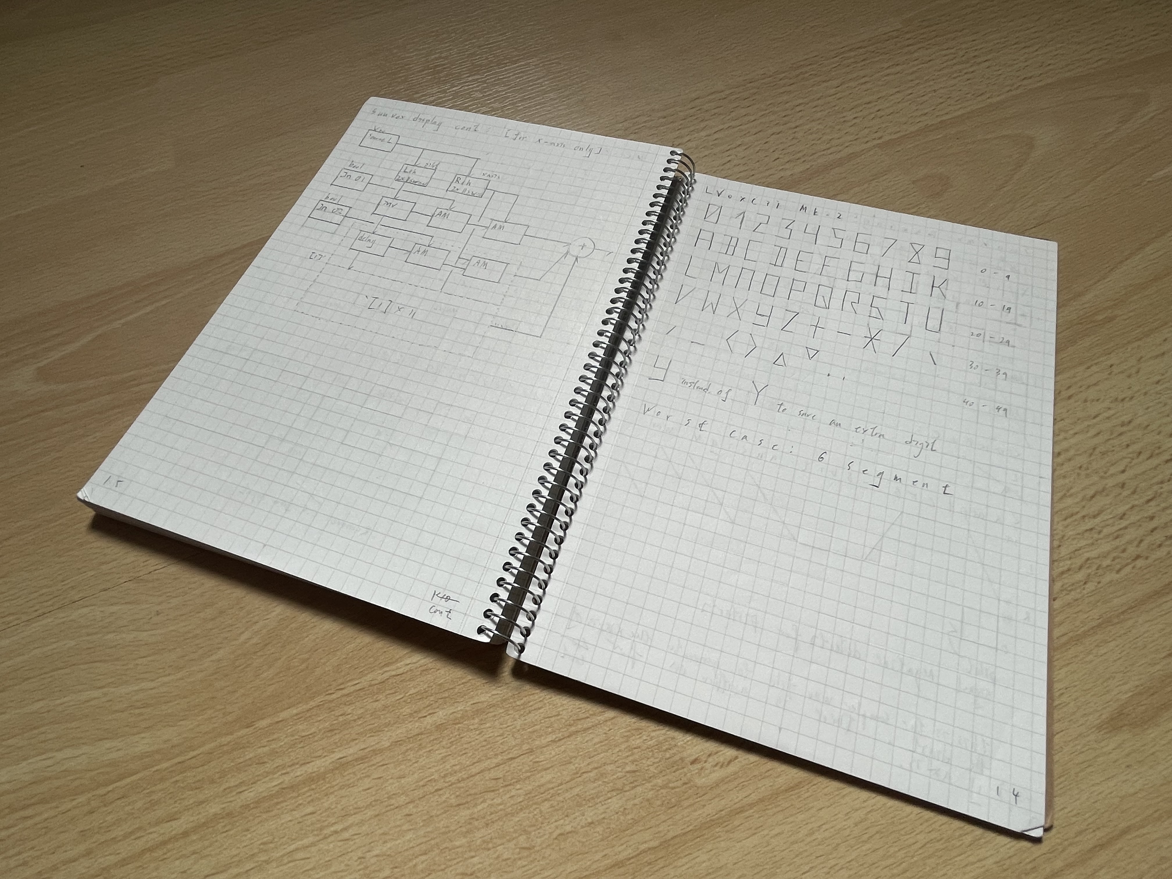
It is better if you have a tablet that features a pen and any note taking app, so that you can take note in there instead, to save paper and to have better time for corrections.
Text editor
Drawing prototype is fast using Notebooks or tablets, but it is otherwise for creating text based ideas; for that reason, you also need some kind of text editor to writing down your logic behind your contraptions. In fact, a simple notepad may does the job, but it is not intuitive to use due to the lack of functionalities. Thus, we may seek some other alternatives. Notepad++ is always a great start since it offer mono-space fonts, better text editing features, and caching your unsaved work. If you are someone who feel comfortable with markdown format, Obsidian with monospace font is a great choice because you can quickly formatting your idea more clear.
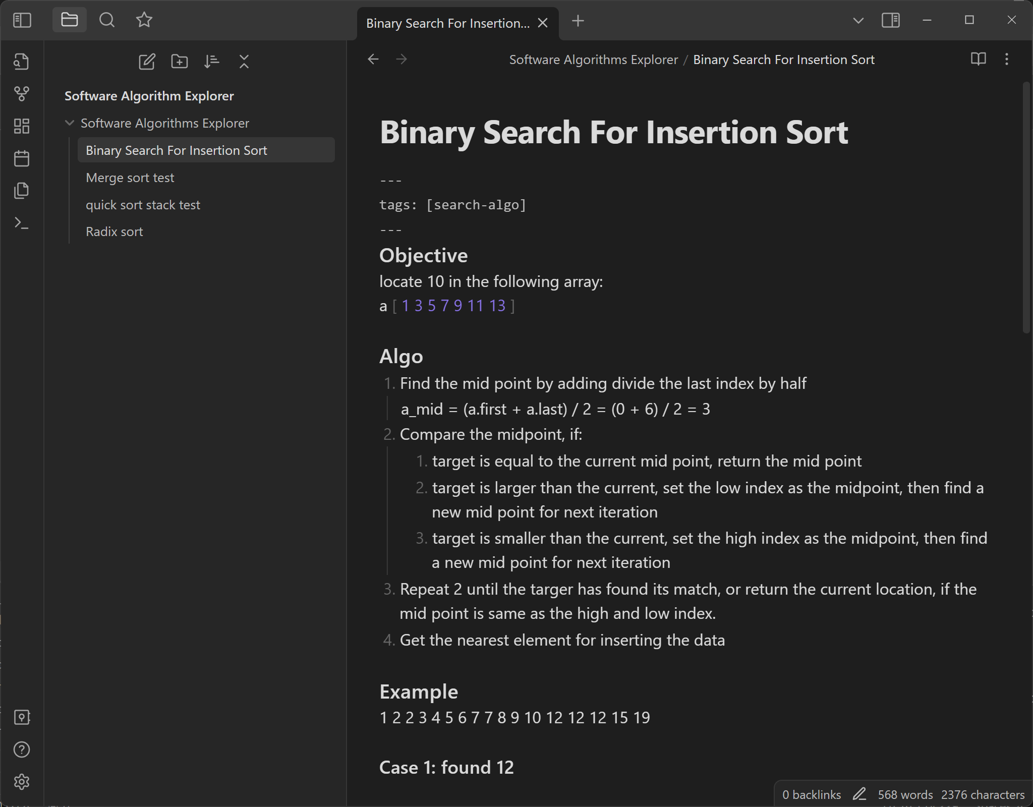
Fun fact: Just got a laptop with Windows 11 recently, and I found that notepad have gotten some improvements like dark theme, tabs and caching. These great enhancements also makes notepad a good options to jot down your notes as beginners.
Diagrams Editor
Beside hand-drawing them, you can also use some tools for create diagrams. There are a few different ways, the easiest way is to use diagram.net, so you can draw some common diagrams like flow charts or sequence diagrams without installing anything software. Besides, you can also install libreoffice, using their draw tools; however, my favorite tools is still obsidian, which it also offers Mermaid Charts, so you can use markdown for your diagrams.
And obviously, SunVox
Nothing is better than using SunVox itself! When you create your logic structure, you may open a SunVox project and build a subset of the whole project; not only this can reduce the complexity for testing, but also it is easier to undo the mistake and use it in your future projects by copying them. Hence, start small, then put them together to form the complete contraption. For example, I have separated project for registers and program counter, so I can have a separated copies for my future projects:
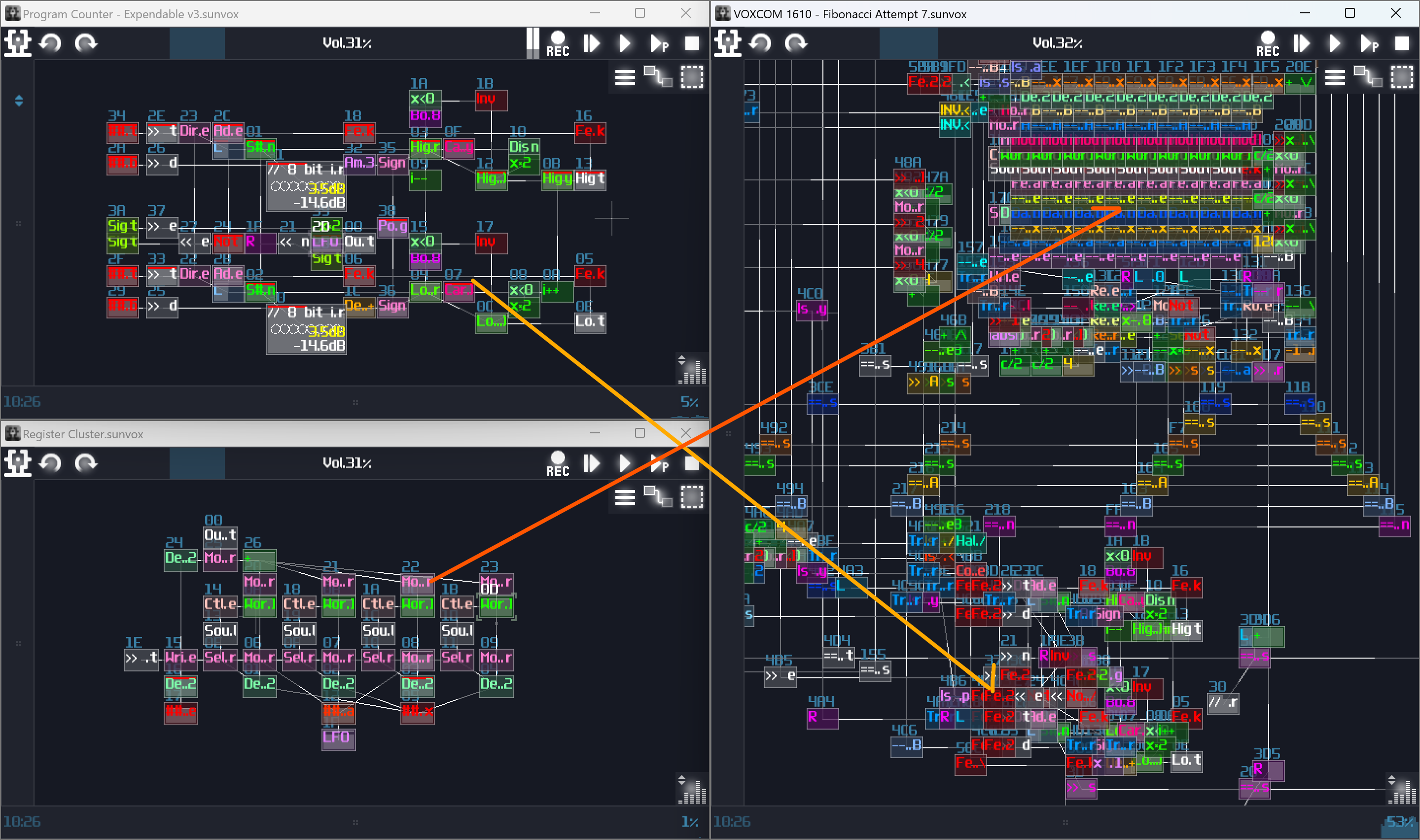
Conclusion
These are some of the common tools I used for planning my projects, and I will tell you about how use some of the commonly diagrams to plan your projects, starting from flow chart.
Example 1 - Unfair Dice
To provide a cleaner demonstration for individual components, some of the modules might be moved into different locations.
Overview
In this Chapter, I am going to show you how to use the concept in the previous chapters, to build a simple siz face dice which you can roll with keypress.
Planning The Project
To build a dice which can accept user input, we need to identify the components:
- A randomizer generates number ranging from 1 - 6
- An input for taking users' entries
- A timer for the dice animation
- A memory block to store a random value once the timer times up
- A display element to show the dice dots
With all those components, you may try to come up with a flow chart, to see how the logic flows:
As you can see, in this project, I would expect a user pressing key, and it triggers a timer with the midi signal which it updates graphics based on the randomizer. The timer counts until it has reached the time limit. Once it times up, it send a write signal to a memory while it records the last state of the randomizer, while changing the display showing the dice value based on the stored value in the memory.
Once you have a clear flow of logic, you may move on to the next phase.
Input
To prevent user breaking the contraption by rapidly pressing the input, we need a SR latch, after a full volumed, monophonic DC generator. Remember to leave a AM modulator for the resetting the SR latch:
Timer
The main timer comes after the input, which is a simple rising edge monostable (5 second in this case).
Randomizer
Even though our dice might be a bit unfair, without a randomizer to randomly pick a number, the dice will be so boring because the state of the dice will be highly predictable. For the ease of building a convincing randomizer, we can use 5 LFOs in random mode, feed with a constant +128 DC offset. After that, we can normalize the output of the LFO such that they can select a value ranging between -128 and 128 DC unit by doubling the gain with subtracting 128 DC unit, and send the signal into individual negative detectors to return a signal only if the normalized LFO generates a negative signal. After negative detection, we take that output and convert it into 1 DC unit by setting amplifier's volume to 2, with absolute mode; by doing that with a summation, we can have a range from 0 to 5 for a decoder that renders the dice graphics. Thus, the randomizer is shown:
Memory Storage
We need to record the final value after the timer times up, we may use an 8 bit D flip flop we have learnt before to store to dice value as shown (The right most green module):
That's it! It is just a single 8 bit D Flip Flop, received the randomizer output as data input and the timer output as Clock signal. Since the D FLip Flop in the toolkit is falling edge triggered, it only assign a value only if the timer goes off.
Decoder
We need to build a decoder to bridging our aforementioned logic structure and the upcoming display circuit, converting an integer value into individual signal paths. The decoder is identical to what we have build in the fundamental sections, with additional two modulator before the input of the decoder that are used for selecting signal between the memory and the randomizer:
Display
Displays are always the trickiest part of any SunVox logical gadgets because of the restrictions of the oscilloscopes, but don't worry, let do that step by step. For now, let's have a look to the classic 6 sides dice face:

If we stack all the faces, you may find that some of the dots are overlapped to one another, and there are only 7 unique dot positions, forming a horizontal H shape. That means, for a dice face, all we need is printing 7 enlarged pixels individually in their corresponding locations by doing translations (I have group the logic into a single module for the cleanliness, and you may find the same module in the graphics toolkit):
![]()
At this stage, all 7 pixels are in the correct positions which top and bottom have three evenly spaced pixels, along with the middle pixel; however, the position is a bit off, but we can fix it at the final stage. With the 7 pixels, we need to find a way to print the correct dots based on the decoder output; therefore, we may attach an modulator after each pixels and map the correct pixel with the output of the decoder as shown:
With our stacked image, we can already see that the dice faces are properly shown, but if we want to fit that into a metamodule, we must squeeze all the pixels into a single output module; thus, we need to do multiplexing with a LFO in square wave and a group of delay modules. For the ease of calculation, we may set the duty cycle of the LFO to 228, which the pulse only stays on for roughly 1/8 of the time for each segment, while the delay time of the following segment is the multiple of 8:
Finally, with that merged image, we can further fix the scaling and sizing before sending the graphic to the output module.
Additional Changes
We have pretty much completed all the basic components of our dice, but we need to connect all the components to make it work because the current dice can't reset itself and switch display between the stored and randomized result, so we must do the following changes:
To reset the input latch, seemingly, we can reset SR latch by setting sending the state of the time since we have reserved a modulator for the reset sequence; unfortunately, since it requires a pair of feedback modules for completing the cycle between the timer and the modulator, introduced a delay. That delay causes the SR latch fails to be triggered since the timer is not fast enough to create a feedback loop for the latch. To solve the issue, we also need our signal input to engage the modulator for switching the latch on:
Lastly, we need to toggle the readout between the D flip flop and the randomizer, so we need a NOT gate receiving the signal from the timer and connect the output of the NOT gate to the modulator after the D flip flop, otherwise for the modulator for the randomizer which directly from the timer. With that configuration, when the timer is on, the choose the randomizer path for rendering the dice, otherwise to the D flip flop:
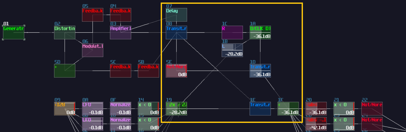
Final Result
That's about it! if you press the signal input module, the module triggers SR latch to prevent user spamming the input to break the contraption, while engaging the timer to play a random sequence. Once the timer has timed up, the D flip flop takes a value from the randomizer, and print the result with the corresponding dice face:
As the name suggested, it is not a fair dice because it often stops at 3 and 4. To make a better randomizer, we could calculate the remainder of a larger number, but that will be another story since that is far more complex than the current design.
Fun fact: I was so lucky to roll a 6 in the screen recording, and this was the first time and the only time I have ever rolled 6 with this dice.
Conclusion
Alright, you should able to know the thought process of how to build contraption which we first consider the logic flow of the contraption, and to breakdown the contraption into a smaller components serving for different functions. After we have completed all the individual components, we can connect each subgroup to form a bigger structure.
Example Project:
Example 2 - 7 Segment Display Counter
To provide a cleaner demonstration for individual components, some of the modules might be moved into different locations.
Overview
After we have built a dice, let's focus on the most common form of display, the 7 segment display. In this example, we are going to build a 2 digit counters that counts up.
Planning The Project
To build a counter, we expect the following features:
- two counters stepping from 0 to 9
- the counters should know when to step back to 0
- the right digit (the ones) should know when to carry the digit
- contain a display that prints the two digit
After we know the basic components, we can draw a flowchart to see how the logic flows:
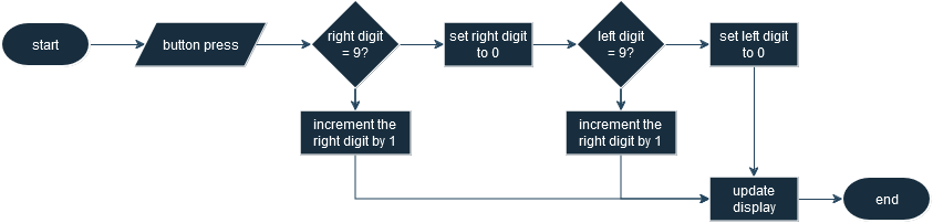
Seems the logic is not complicated because all we need to do is to bump up the counter or carry the right most digits to the left, so let's heading to the implementation.
The Counters
Obviously, we must have some counting mechanisms to count the number, so we are going to build two falling edge triggered counters which can simplify the carry logic. There are two ways to build a counter, and you may use either approaches:
T Flip Flops Based
The first approach is to use a series of T flip flops, and you can simply chain 4 flip flops as shown:
After you have mapped each output of the flip flop to their corresponding DC unit, you already have a base 16 counter:
However, since we are doing a decimal counter, not hexadecimal, we need to prematurely reset the counter to zero once it reach 10; thus, we need to build a reset structure when the flip flops hit 10 in binary. using logic gates, feedback, sound2ctl and multictl:
As you can see, when the flip flop chain hit 1010 (from right to left where the right most flip flop is MSB), it triggers the bottom AND gate such that the AND gate sends a reset signal for the T flip flops to do a hard reset, limiting the counter to count from 0 to 9.
Accumulator Based
T flip flop is intuitive for people who learn about classical computing, and it is easier to manipulate individual bits, but T Flip Flop is not space efficient in terms of file size because it is a metamodule containing the memory circuit and a monostable. If you want to use less number of modules, or you only care about integer operation, you may do an accumulator.
Initially, you need to build an accumulator, consisting a falling edge monostable and a delay based memory with the delay time aligns to the monostable:
Nevertheless, you can definitely spot a problem that the accumulator goes out of bound. To reset the accumulator, we need to set the feedback of the delay module to 0 when it hit 10. In the following example, we can subtract 10 from the delay using an amplifier in negative absolute mode, triggering the negative detector, and only if the memory cell hits 10, it disables the negative detector and breaks the internal feedback of the memory cell to reset. Since the reset sequence might have display 10 in a short amount of time, we need to overwrite the output with 0 when the accumulator is temporary 10, detected by a NOT gate attached after the negative detector, along with normalizing the output of the NOT gate to 10 for offsetting the output; thus:
Carry Logic
Once we have a counter, we can now expend with an additional digit by duplicating the counter your have made previously. For this example, I am going to use the T flip flop based counter for the tens digit, while the accumulator based for the ones; however, this is a BAD practice and it should be discouraged since you should duplicate the same structure if there are multiple operations that does the same. Implementing the same logic with different variations will make debugging tricky, but because all these screenshot you have seen will be exported as an example project, I have to mix the counter instead:
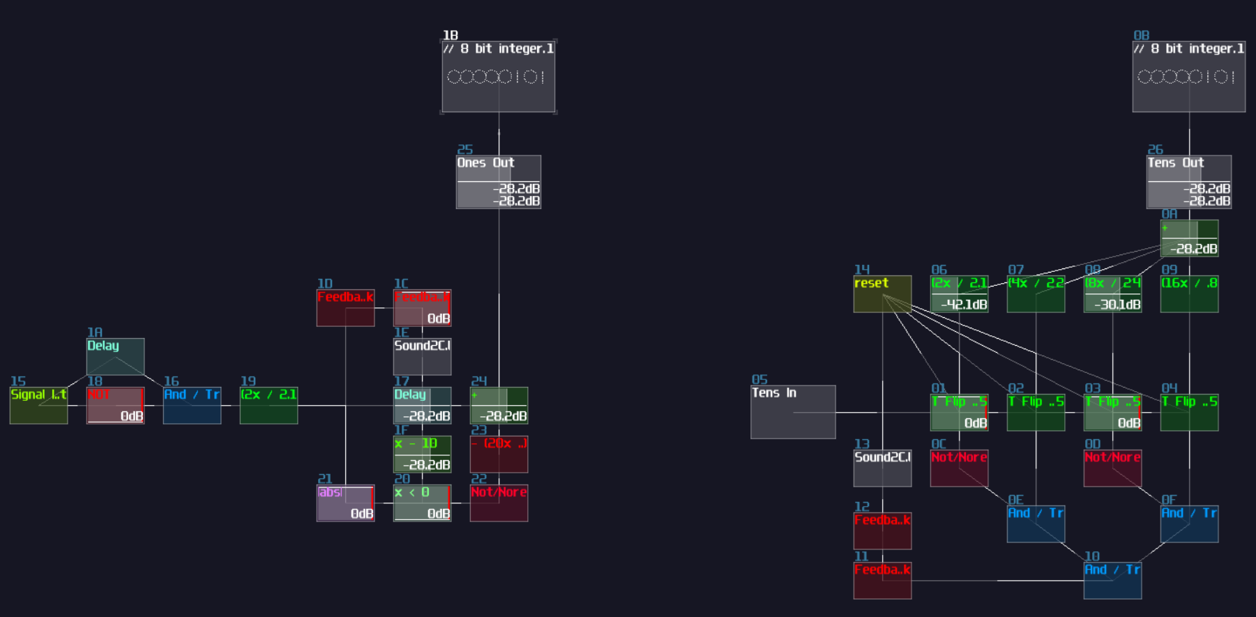
As you can see, I have only placed the two counters side by side, but I have leave a gap and aligning the sum module of the Ones counter (the left counter) with the input of the Tens counter (the right counter) so that we will have a smoother experience on building the carry logic; otherwise, you will need to move the module groups a lot, or you will create a messy project.
To carry the digit from the Onns counter, all we need to do is to fire a signal only if the memory block from the Ones counter is 9, subtracted with 9 using an amplifier in negative absolute mode and with -9 DC unit. Along with a negative detector and a NOT gate, it will send a signal only if the memory block hits 9, and since our counters are triggered by falling edge, the Tens counter steps only at the moment when the Ones counter no longer be 9, which is at the moment of stepping from 9 to 0:
That's about it, this is all of the logic for the counters, and let's build some 7 segment displays.
7 Segment Display
7 segment (or any segment) displays are crucial for displaying the results of your calculations or rendering texts, so I will explain this element in details so that you can build your own segment display, but first, let me show you a 7 segment display to see how it works:
Obviously, 7 segment displays consists on 7 line segments, forming a 8 like shape, and you can control individual segments to display certain characters; nevertheless, not all characters can be rendered on a 7 segment display, and this is why display with higher number of segments do exist.
To build a 7 segment display, we start by using a LFO playing in saw wave, but because the saw wave plays in both channels, it will create a diagonal line. As we don't need a diagonal segment for our 7 segment display (perhaps for the more complicated one), we can individually extract the Left and Right channel to form a horizontal and vertical line as shown:

This already covers the middle horizontal line and the top left segment. To construct the remaining segments, we need to do translation once again, and since LFO generate a signal ranging from 0 and 128 DC unit, we can just move the segments horizontally or vertically by 128 DC unit. The following mapping is based on a standard 7 segment display which segment A starts at the top, traveling all other segments in clockwise, and end with Segment G which is the middle horizontal line. In the following example, I have used a "Rom" module for translating the shape into different location, and they are basically just DC offset control from amplifier but controlling left and right channals individually. You may find the Rom module in the Memory toolkit (Rom -128-128):
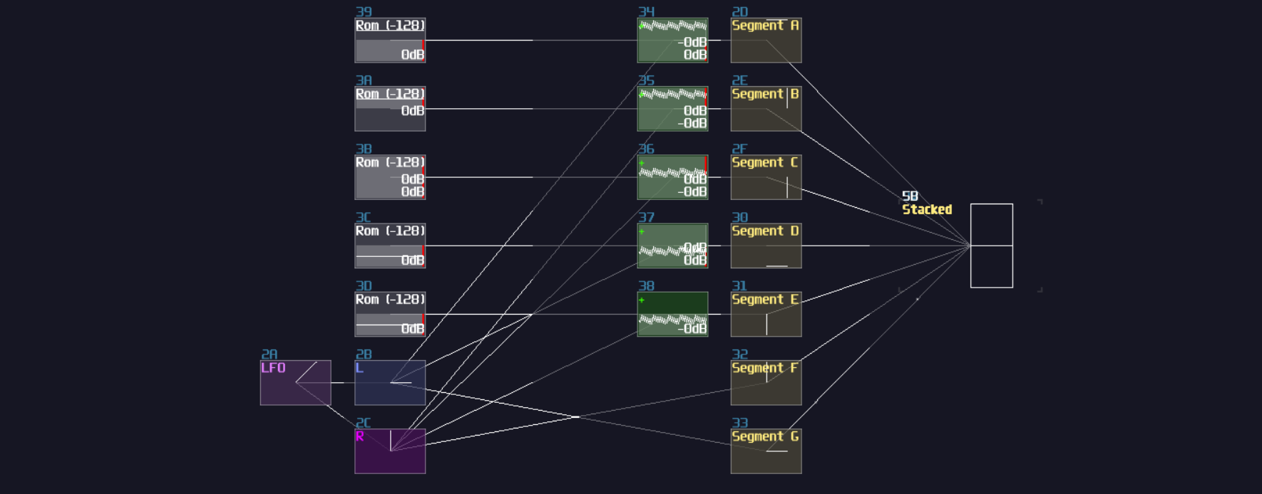
Similar to the dice example we have done before, we now have a stacked image, so we need to append an arrays of modulators acting as transitors for accepting input from the counters, and do multiplexing after the transitors. Once you have done right, every segments will be printed on a single module, while you can control individual segments as shown (signal inputs modules are not required in the final design, just for demonstration only):
As usual, such structure requires a decoder-encoder pairs to convert integer value into displayable format; after breaking down the integers into individual signal paths, we need to connect the signal path into the corresponding segments to represent a correct character as shown:
| IN | A | B | C | D | E | F | G |
|---|---|---|---|---|---|---|---|
| 0000000001 (0) | 1 | 1 | 1 | 1 | 1 | 1 | 0 |
| 0000000010 (1) | 0 | 1 | 1 | 0 | 0 | 0 | 0 |
| 0000000100 (2) | 1 | 1 | 0 | 1 | 1 | 0 | 1 |
| 0000001000 (3) | 1 | 1 | 1 | 1 | 0 | 0 | 1 |
| 0000010000 (4) | 0 | 1 | 1 | 0 | 0 | 1 | 1 |
| 0000100000 (5) | 1 | 0 | 1 | 1 | 0 | 1 | 1 |
| 0001000000 (6) | 1 | 0 | 1 | 1 | 1 | 1 | 1 |
| 0010000000 (7) | 1 | 1 | 1 | 0 | 0 | 0 | 0 |
| 0100000000 (8) | 1 | 1 | 1 | 1 | 1 | 1 | 1 |
| 1000000000 (9) | 1 | 1 | 1 | 1 | 0 | 1 | 1 |
Once you have the correct mapping, you should able to print a number by changing the input of the decoder:
And that's about it, this is how we can build a 7 segment display in SunVox.
Connects Everything and Display Double Digit
"We have built a 7 segment display, but... there is only one digit. How can we print two digits at the same time?" you might ask. It is not wrong that duplicate the 7 segment display is a solution, but this is hugely inefficient; thus, I normally do another multiplexing to quickly switch the numerical value and the position of the digits:
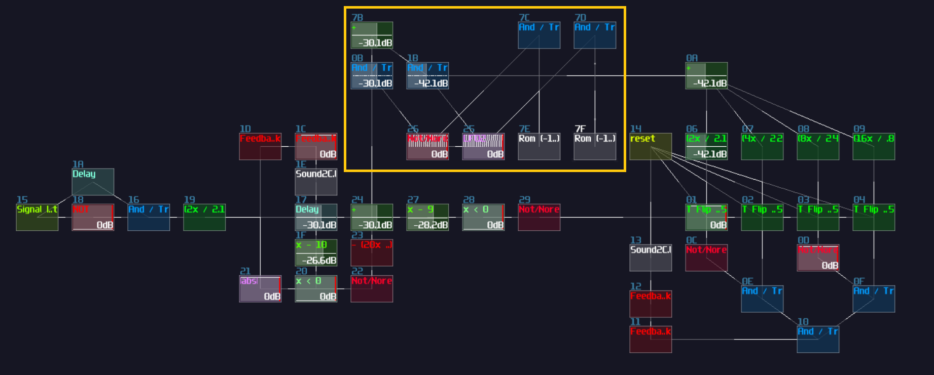
After that, connect the combined value to the input of the decoder, and connect the combined position offset to another add module that connected from the output of the 7 segment display as shown:
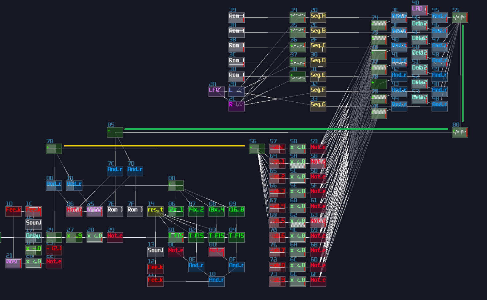 ;
;
Combined the position offset and the output of the 7 segment display, send the data to the output, but currently, the two numbers are overlapped to each other, so we need to change the position offset of their individual digits:
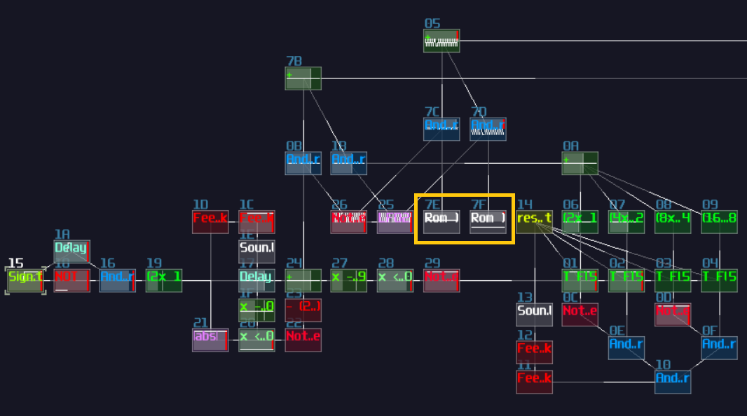 ;
;
Once you have solve the overlapping issue, give the final result a porper scale, it is good to go.
Final Result
This is it! now you have a counter program with a two digits 7 segment display. Send a signal from the signal input, you should able to see the counter incrementing the digits.
Conclusion
Wow, that's a lot in this chapter; hopefully, after this tutorial, you will have more understanding how to build a counter circuit and a 7 segment display.
Example Project:
Example 3 - Plotting N Sides Polygon
This chapter might contains advance concepts and it might be overwhelmingly long due to the number components; if you feel overwhelmed, you may move on to other chapters first and goes back to this chapter once you are ready.
Overview
In this chapter, I am going to focus more on the input and the memory storage by building a polygon plotter which can supports up to 8 sides.
Planning The Project
Since this project is a bit more complicated and requires more input, a flowchart might not work well enough for this application; thus, let us write some users stories to define the main features:
As a user:
- I want to add new nodes for my shape, so I can have any shapes up to an octagon
- I want the nodes to be movable, so I can have shapes more that just a regular polygon
- I want to edit or remove the most recently added node, so I can undo my previous mistakes
Although this might not be the best way to demonstrate user stories which they are usually used for projects in larger scale, breaking down functionality with different role, the user stories above can still give us some directions and ideas to build that plotter. By looking at the story, we can expected that if we want a plotter, we need to add nodes based on the coordination moved by the users, and edit or remove the last coordination. Based on the following features, we can confirm the following components:
- Controller that moves a cursor
- Controller to edit add and remove the last coordination
- A memory circuit for logging the inserted coordination
- A display can print the cursor and the polygon
The Controllers
To build a more complex controller, I usually start with a MultiSynth and narrow down to a specific keys for the specific function, and in this example, we need the following actions:
- move cursor up
- move cursor down
- move cursor left
- move cursor right
- toggle edit mode
- add new node
- remove last node
To fulfil all the features, we need 7 inputs, but since MultiSynth only accept keys that belongs to a piano keyboard, we can't use the traditional WASD or the arrow keys, so let's have a look to the keyboard layout to see if any alternative options:
As you can see, A is not considered as a valid MultiSynth input, so the next best thing is either use 2QWE or SZXC for the navigation. Either one is fine because these two sets are interchangeable due to the ability of changing keyboard octaves in SunVox; Thus, I am going to use C, C#, D and E for the navigation which aligns the aforementioned keyboard entry set. Relatively, instead of using JKL as actions keys used in countless games, you may pick M,. or UIO as alternative, which is B, a higher octave C and D note on the piano keyboard, used for toggling edit mode, add and remove nodes.
After we have defined the input key set, we can move on to add ourselves the first MultiSynth, and this will handle all the possible keyboard entries. With that entry point, we can further attach 7 MultiSynths, corresponding to the 7 inputs we have defined in the previous steps. From the 7 MultiSynth, we need to filter out all the unrelated notes by setting all noteds in the Note-Velocity map in the zero. For example, for the move up operation, I only leave C#5 on, meaning that only C#5 will trigger the operations instead of other keys. Even with the filtering, some modules we used later such as LFO and ADSR can still be triggered, so you have to check the "7E Ignore notes with zero velocity" option for the MultiSynths with the filtering applied:
With the correct filtering, you should see the MultiSynth only triggers the operations only if you play the correct pitch:
Here are just a tip of an iceberg because we also need to make the control fool proof and being more convenient, so I am going to define additional features for each controls:
- if the user hold one of the navigation keys, they fire the operation once initially, and after a short pause, it repetitively trigger the same operations, similar to when we hold a key on a typing keyboard.
- the navigation has bounds, and we should stop the cursor from moving further from the viewable range of the Module Oscilloscope.
- the edit button is a toggle button, and if the mode is active, it display a cursor icon on the current coordination of the current node, or at the origin when a new node is added; otherwise, it should prevents any from of input from other buttons.
- the add and remove button should overwrite a cross on top of the cursor for a short amount of time if the add or remove operation fails.
With the additional specifications, we can arrange the order we decided to implement the logics based on their dependencies; clearly, the edit button should be the last because it overrides all functionalities when the edit mode is off, while add and remove operation relies on the navigation; thus, let's work on the navigation system first:
Cursor Navigation
To produce the behavior of rapid firing action after pausing for an initial input, we may use LFO and ADSR for the timings. For the initial entry, we may use a signal input to generate a constant DC and limit the pulse using a rising edge monostable. For the pause and the rapid fire action, the MultiSynth of navigation operations also trigger an ADSR with relatively long attack, full sustain and no Release so that it takes time to rise to the top and shuts down immediately if the user release the button. Since the peak of ADSR reaches +128 DC unit, we may conditionally send a DC signal only if the ADSR reaches the top, using an amp with -128 DC unit, a negative detector and a NOT gate. With the output of the NOT gate, we may use an LFO to periodically sending a pulse, and combine it with the initial pulse:
After that, since there is only a single input and output, we may wrap the structure into a MetaModule so that it easier to make duplication and easier to maintain the overall project, and don't forget the set the input module aligns to the internal MultiSynth:
After the triggers, we need to reduce their signal strength down to 1 DC unit, using an amplifier with the volume of 2, and remove one of their channel according to the direction of the operations, followed by a summation. After we have summed all four directions, we reserved a transistor for the edit button so that all the operations are effective only in edit mode:
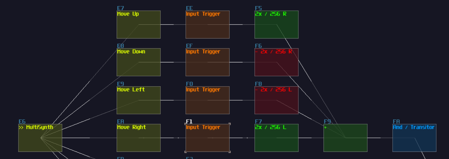
We may pause here because it will be a bit tricky if we insist to build the complete control system without other components, so we have to focus on most of the input's dependencies first, all the memory circuits.
The Stack
The user want to create 8 coordination at most, and edit and remove the most recent coordination; for that requirement, we may use a stack.
Stack is as data structure that works in a LIFO (Last in; first out) manner 1. In layman terms, it is like when you stacking up some plates, you always put a new plate on the top of the stack, and when you want to grab yourself a plate from the stack, you always takes the top one.
To built a stack, we may starts from their memory cell first because it also requires to have additional logics, and for now, let's build an accumulator first which is made by a delay memory cell and a rising edge monstable, synced with the identical delay frequency; keep in mind, our input entry also have a finite length of pulse, and we must ensure that the delay time used in the memory is shorter than the incoming pulse duration; otherwise, incomplete and noisy write for the memory will occur; thus, let's set the delay time of the memories in 1 Sample unit. In addition, since the input consist of an 1 DC unit pulse, with the modulator in the rising edge monostable, this will further divide the signal strength by 128 resulting in an inaccurate value. To solve the issue, the pulsing part (the delay side) of the monostable must be feed with a +128 DC unit pulse, and we may use an absolute inverter and a negative detecter with inverted output.
Built the writing operation, now we can handle the clear operation which is straight forward that you only need to take an input and convert that constant DC signal into a midi by triggering the state controller of a ctl2note. Using that midi signal, we can play a MetaModule containing a single line of "stop the module command (xx)" pointing to the output module internally that will send the stop signal externally for the delay memory to clear everything:
Owing to the specification, we need to support up to 8 nodes to form an octagon, so we need 8 duplications such cells:
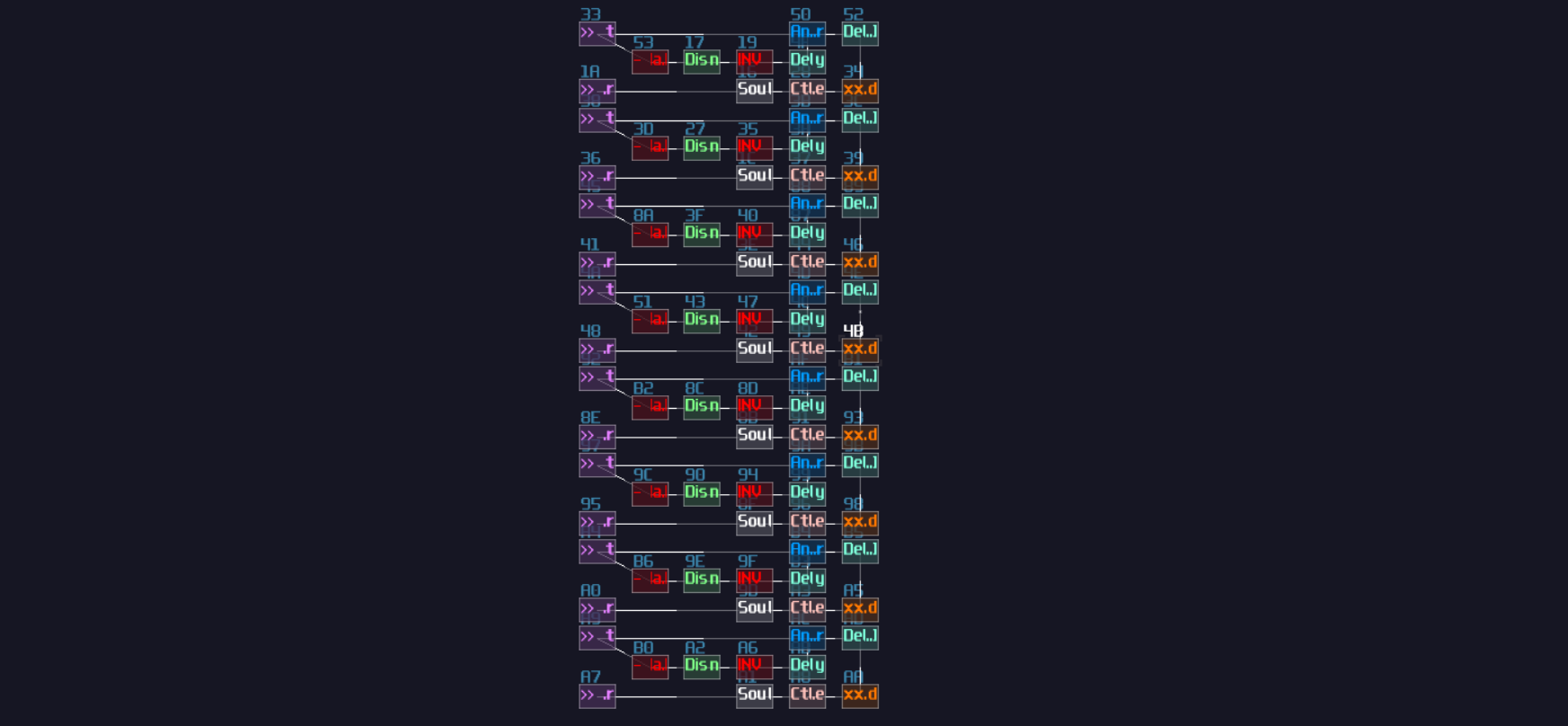
To access the memory cell individually, we need decoders. The decoder has multiple purposes, writing, displaying a cursor, and perform a boundary check for a specific memory cells, so we need three set of transistors, two before the input which they are used for writing and cleaning data, and one set after the output of the memory cells:
The current structure alone is still not a stack because it misses two important characteristics: push and pop an item. Push operation means to add a new data at the last location of the memory slot, just like how you stack things where you always put your last item onto the top; meanwhile, pop operation is to remove the most recent item you have added into the collection. For our polygon plotter, thing works similarly, press the add button, we add a new node, versa when we press the remove button, but since we don't need to care about what happened to the removed value, or a specify and value during adding a new item, we can squarely set the removed memory cell to zero without returning the popped value; thus, based on our original memory slot, all we need to add a set of counter to keep track on the index
Firstly, we need two entry points for the push and pop operations, both take +128 DC unit as input signal, and split both of the signal paths such that they have an additional paths that regulate to values to +1 and -1 for push and pop respectively.
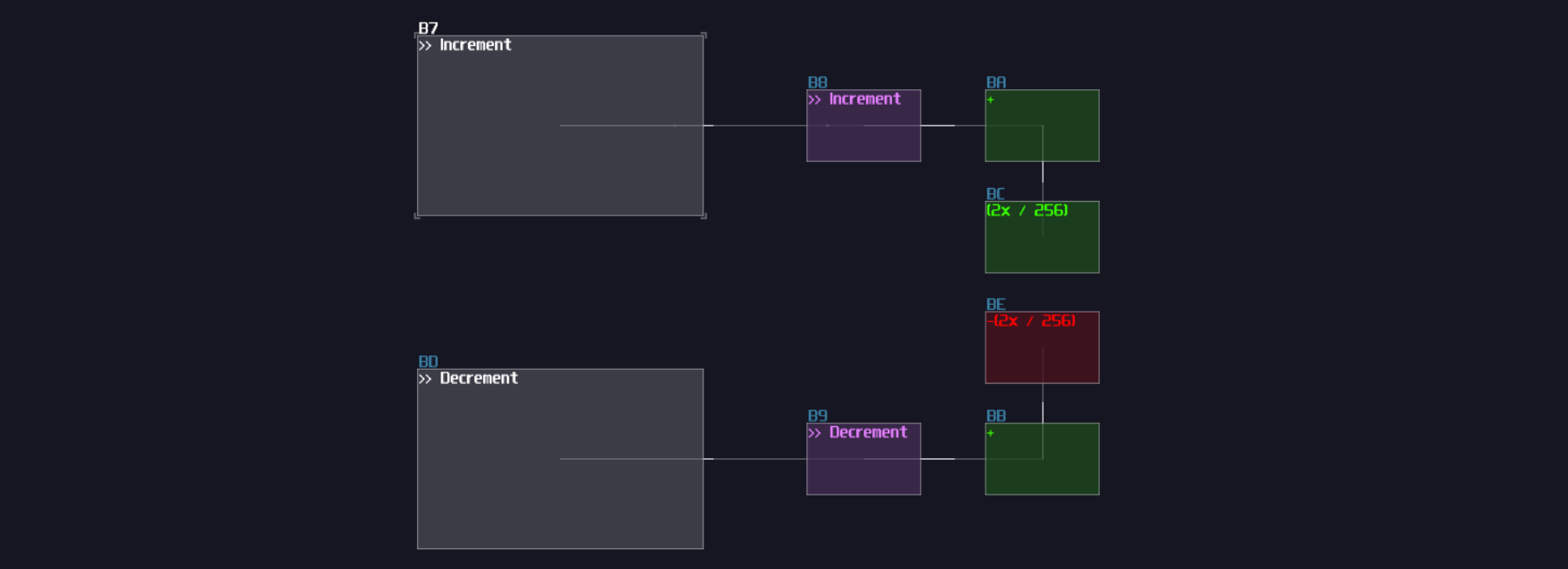
What goes after the entry point is a counter. Right after each of the regulated output, we may reserve a transistor for logics to prevent users adding or removing too many items that lead to an invalid state; after the transistor, we may copy another memory cells as shown:
As you can see, each input has a reserved transistor, and we need to build a feedback loop to lock the entry point such that they can prevent index getting out bound, using negative detector with a DC offset:
The counter has completed, let's connect the output of the counter to the input of the decoder of the memory clusters:
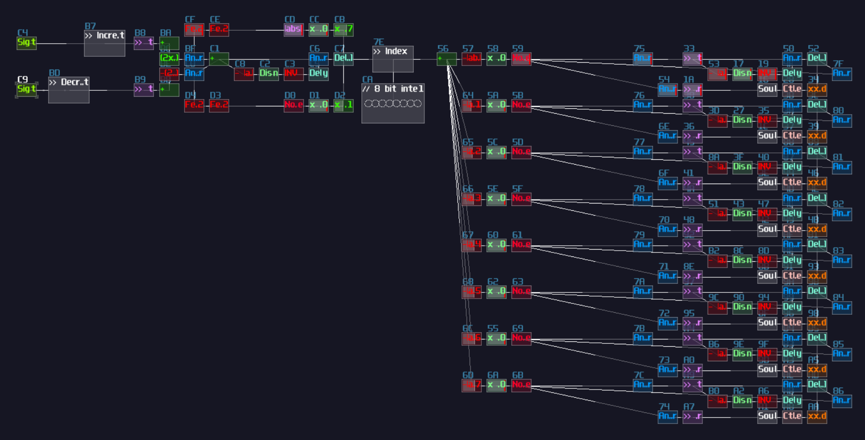
It is really close to the completion of the stack memory, and all we need is to figure how to connect the two inputs to for the stack. Nothing is changed for the input because we only need to increment the index for the next element, but for the output, it will be trickier which you will encounter the first race condition for your contraption. Race condition is a problem that the order and the timing of operations affect the result 2. In this example, since counter decrement and data clearing happens at the same time, it might unexpectedly erases the previous memory cell. To prevent the issue, we need to send a regulated pulse such that the clear and decrement happens in the correct sequence without overlaps; thus, we need a monostable and delay to separate two operations. Here is the slower version to demonstrate how the sequence works:
From the illustration above, you can observed that the monostable first generates a pulse to cleaning the memory cell. When it has finished, a delay is introduced to form a separation before the decrement happens. This configuration ensures that clear action must be done cleanly before moving to another memory cell. After set the delay time of the timing circuit to 5 ms, we may connect the decrement signal output to the counter and the clear signal path to the each transistor output of the clear port to the memory cells as shown:
Finally, for the data entry, we need to connect a data path to each of the transistors that connect to the data port of the memory cells so that the controller have a port to send signal to update the memory cells:
Complete The Remaining Controls And Connect To The Stack
Since we have completed the stack, it is easier for us to complete the remaining circuits. Back to the controller, because we know that the "Add Node" and "Delete Node" belongs to the Push and Pop operation of the stack, which is time sensitive, we need to find a way to prevent users spamming the controls. To make the control less spammy, we may use an inverted ADSR trigging a negative detector so that even if the user rapidly press the add and remove key, the controller still considers that is a single pulse:
The spam prevention mechanism is applied after the add node and remove node operation, along with a transistor. The transistor are manipulated by the edit toggle button which is a T flip flop, so are the transistor from the navigation system so that they are operational only if the edit mode is on:
With the controller, connect the transistors based aligning to the functionality of the stack memory: the navigation system links to the data port, the add and remove node connects to the increment and pop respectively:
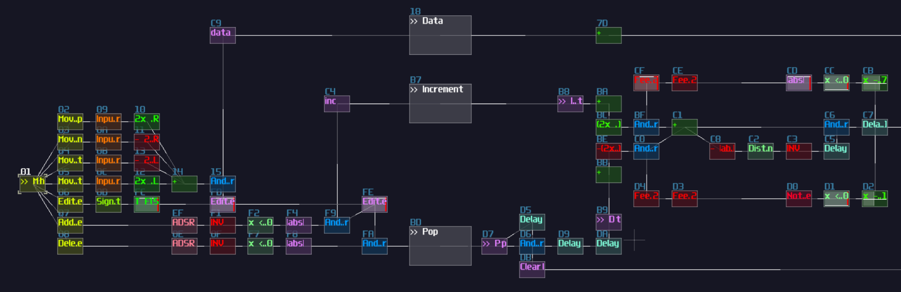
If you have done correctly, after pressing the edit button, you can see the navigation system update the first memory cell, and if you press the add button will update the second memory cell and so on. Pressing the delete button will clear the the most recently added memory cell and the counter moves back to the previous memory cell for editing.
Boundary Check For The Navigation
For all the control logic, one problem remains. If you hold one of the navigation buttons too long, the cursor location will go outside of the oscilloscope, and it is easy to get lost if both of the coordination are outside the range; thus, to solve the issue, we need to apply a boundary check which is similar to what we have done for the stack, except that it need to explicitly handle both channels.
In this example, let we set the boundary as:
- ±200 for horizontal direction
- ±128 for vertical direction
After that we need to split the memory cell into left and right channel, using an amplifier extracting one of the channel and centralize the signal by setting the stereo width to 0. Because setting stereo width averages the power of both channel while we have nothing to their opposite channel, the volume is reduced by half, so we need to double the gain to properly extract a channel into a mono signal path:
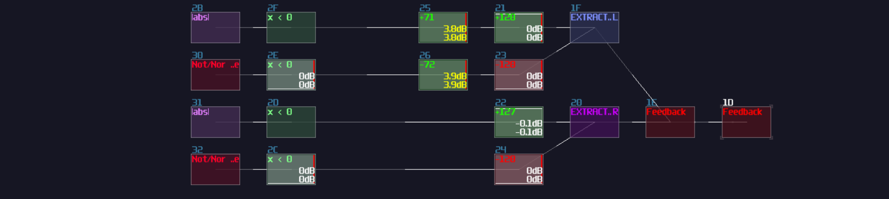
After we have the bound check, we can group all the transistors at the output of the the memory cells and connect the grouped signal to the bound check:
After we have the four indicators, we can insert additional four transistors after input triggers so that when the cursor gets out of bound, it cut the input of the specific direction, and since we want our four input On by default, each additional transistor needs a not gate:
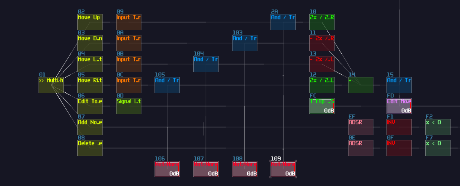
Finally, connect the boundary indicator based on the direction of the control, and we have completed all of the control logic.
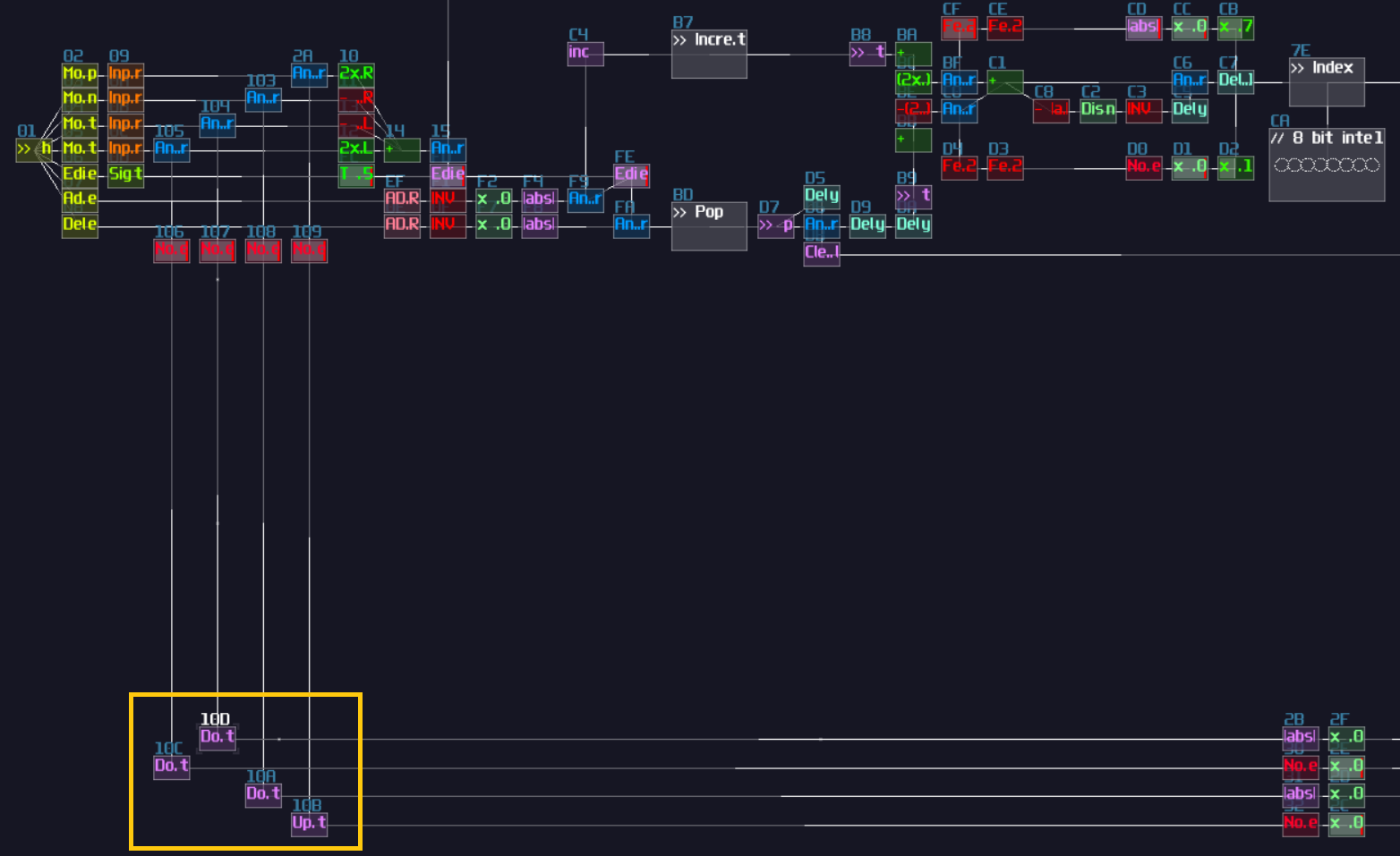
The graphical Components - Polygon Plotter
We are halfway through the whole project by completing all the control circuit. In the following part, it is all about graphical components.
To plot the polygon, we need to print multiple lines, so we need to print a line given two points which we may build the structure we have learnt in the graphic section as shown:
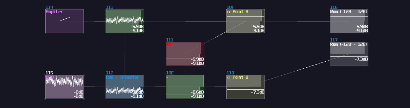
Due to the space concern for the screenshot, I have to mirror the structure so that the final result can fit within a single screen, but in practice, it is better to keep the input and output into the same orientation unless it is a feedback mechanism. After that, it is all multiplexing again, but we have two problems:
- We need to find two points that the first point is the previous point of the second point
- The number of points are dynamic
With this two requirements, we seem to face a problem because with the multiplexing knowledge we have learnt, they all handles fix number of nodes; however, in this example, the node size are dynamic such that the last node are always links to the first node. For example: if there are three nodes, the the third node always forms a pair with the first node, and if we add two more new nodes, the last node has became the fifth node which it will pair with the first node. That means, using LFO and delay doesn't work well since you have to dynamically calculate the length of the delay and the LFO pulse and dynamically block some of the unused delay module to prevent overlapping which is complex and in accurate since is it hard to calculate the delay time based on the duty cycle of the LFO. Nevertheless, there is a more convenient way to do multiplexing dynamically. Thus, let's have a look to a Square LFO with a distortion.
Remember how Negative Detector works? It sends a negative +128 DC unit if the incoming signal is negative. This works because we have set the bit depth to 1 which it has quantized the input into a 1 bit signed integer, which is either -1 and 0:

Likewise, if we increase the bit depth to 3 bits, the distortion will quantize it to a 3 bit integer, ranging from -4 to 3:

With the same principle, we can set the bit depth of the distortion to 8 to quantize the signal into a 8 bit signed integer which aligns to the DC offset steps size of amplifiers. With the quantization, we can feed a LFO signal regulated by a transistor, bound by the another constant DC for the maximum value of the counter:
From the illustration above, you can observed when we increment the memory cell by one, the counter counts based on the given upper bound defined the memory cell, but there is one problem remains: How to build the second counter such that the last element always points to the first element regardless the node count. To do this, the easiest way is to split another output with another amplifier with adding 1, so the second counter is always being one higher that the first, but when the second counter reaches the maximum, it forcefully set the output to 0, bound by the index counter so that the counter can be wrap dynamically; thus, you will ended up with the following structure:
That's about the dynamic counter, and this is huge because instead of dynamically changing the pulse and delay length in real time which can be tedious and inaccurate, two decoders is all we need with this dynamic counter; meanwhile, although the counter vary the frequency of the counting action, since we use that for multiplexing, which it doesn't require a constant time, the problem is negatable; thus, we have successfully transform a problem into a simpler, more intuitive form.
After all, they are all about decoders, but before that, let's add a pair of transistors for each output of the stack memory cell, and group all the transistor groups into two distinct data buses so that they return two distinct selected points for the line plot:
For the decoders, we need two set of them, and for the sake of connectivity clarity, I build two groups of decoders in an alternating pattern as shown:
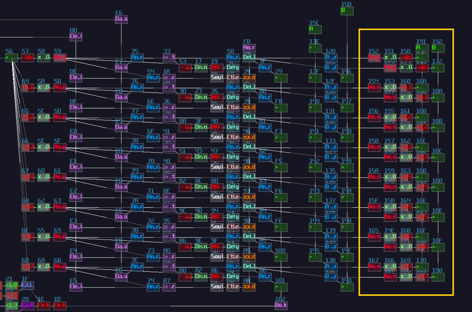
From that, we can now work with the counter, but since the initial condition of the contraption has one node by default, we need to add one to the transistor that set the upper bound of the counter and the bound check for second counter; thus, we will have following (the order of the counter doesn't matter for this case):
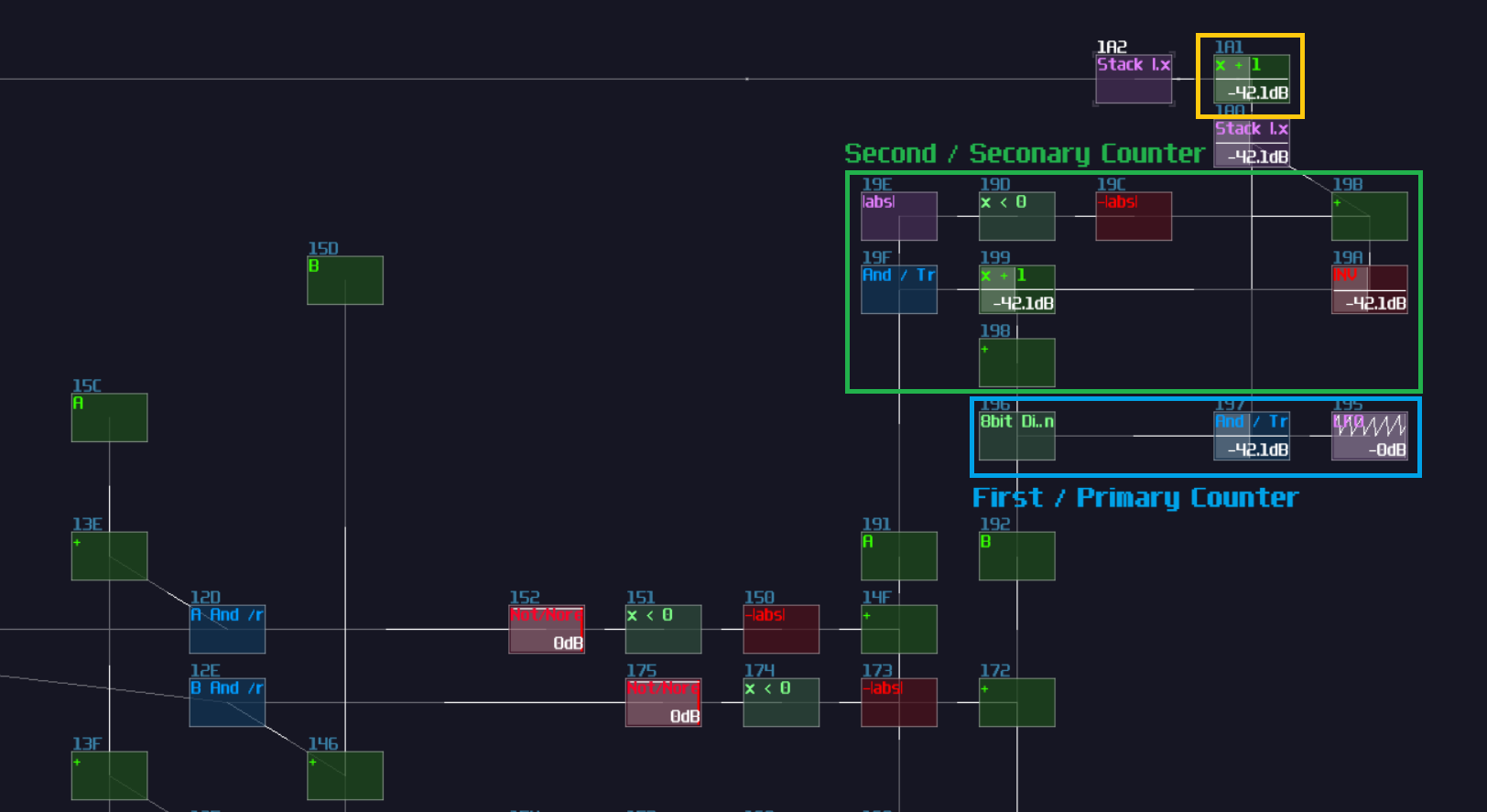
Once the counters are set, remember the two data bus we have created earlier after we have implemented the dynamic counters? We can finally connect the output of the two buses into the line plotter. For someone who are inpatient, if you have already played around with the plotter, it already works!
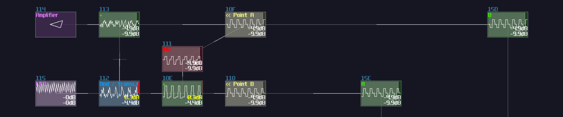
The Cursor And Validation GUI Elements
Technically, we have completed the core feature of the plotter, but as the requirement has stated, we still need to implement some features that enhance the user experience (UX), building a solution that is more intuitive to use. Therefore, according to the specification, we need to build a GUI for the cursor when the contraption is in edit mode, along with a simple cross if if fails to add a new node.
There are many way to make a cursor icon, but for the simplicity, I am going to make a "Sniper Scope" like element which consists a cross and a circle:
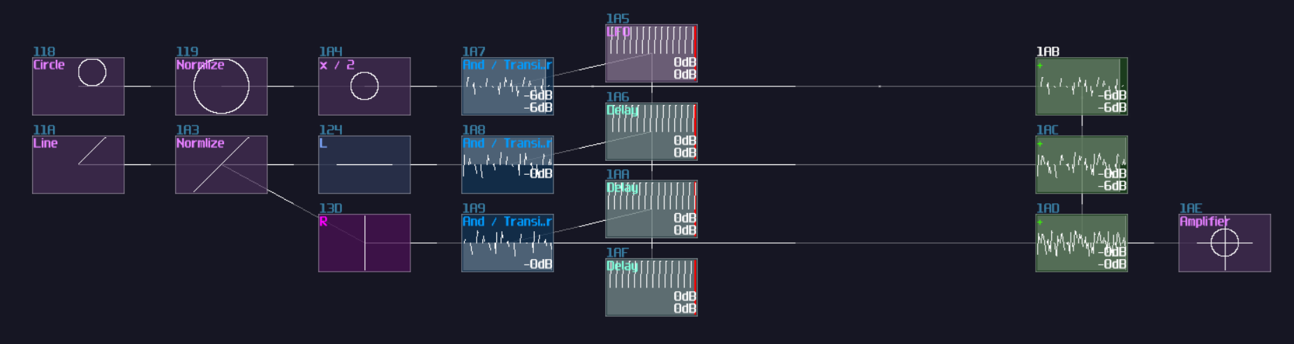
The reserved space are no coincident because we may build a cross based on the existing structure with reflections:
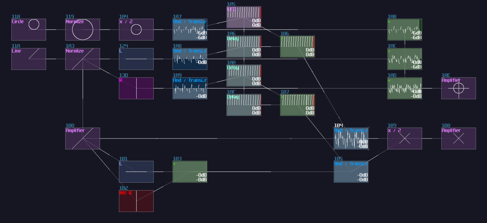
The cursors are a bit too large, taking the whole oscilloscope, so we may use another amplifier to reduce the size. After that, we need to add a logic that can detect any invalid add operations so that the cross will temporarily overwrite the cursor. To handle such case, we need to extract two signal paths where:
- if user has pressed an add operation in the edit mode
- if the stack has full
Thus, we may extract an output where users fires an add operation signal from the entry structure, while another output from the max boundary check for the stack like shown, and use an AND gate to see if both condition are true:
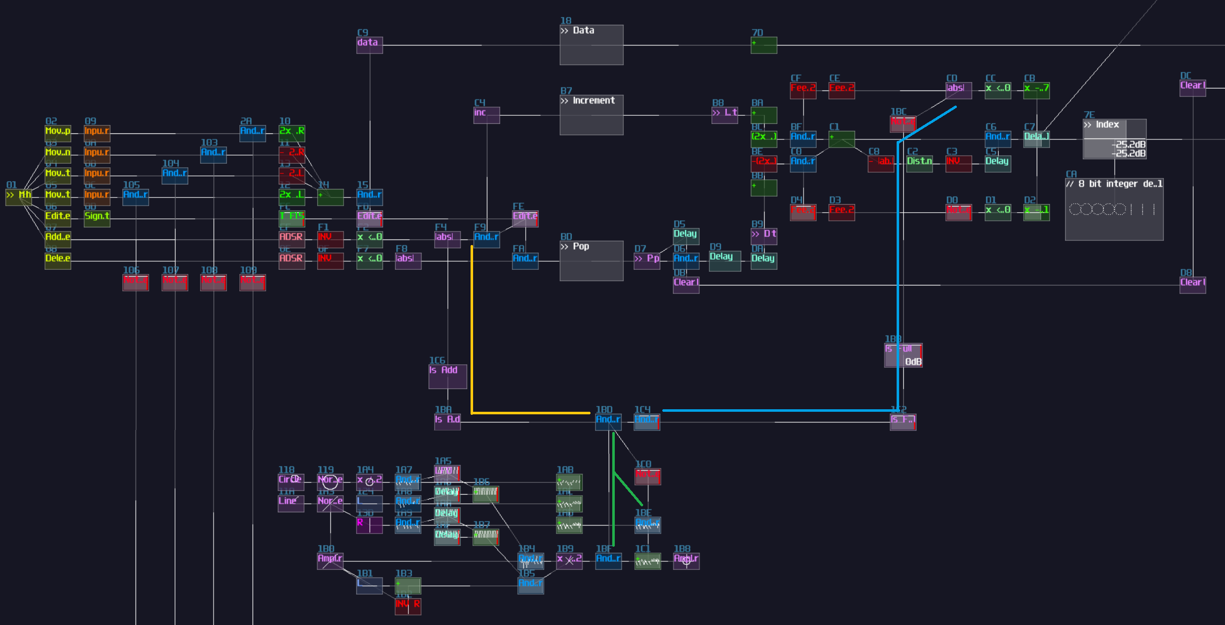
"But why did you put an AND gate that isn't really controlled by anything?", you may wondering. That additional AND gate is to handle an edge case when the stack index reaches the maximum for the first time which it should be a valid case, but with the current set up, the validation throws an "X" even for the valid case. Therefore, we need to do additional checking before mark the user action as invalid. To solve this issue, we need an SR flip flop which the set and reset port are triggered by falling edge monostable from the user input pulse and the max boundary check respectively. To prevent the user input writing the SR flip flop multiple times, we need a feedback loop to cut the signal path if the flip flop has already been written:
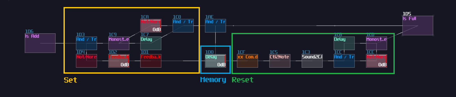
Once you have built the additional check, connect the input to their respective bus, and the memory block connects to the additional, unconnected transistor like shown:

Once you have done right, the cross overwrites the cursor if you attempt to add a new node when the stack is full.
And Finally, Putting All the Graphical Elements
After we have completed ourselves some cursors, we can finally connect the plotter and the cursor. First of all, extend the edit indicator to the top of the project, so it will be easier to build the last rending mechanism:
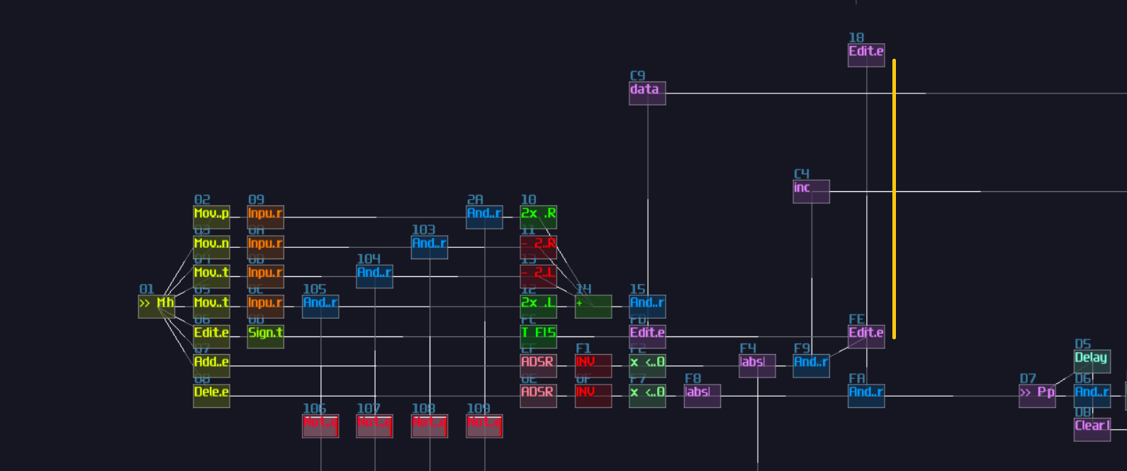
On top of the extension, we need to build our last multiplexer, and this multiplexer is a bit different because it is bias towards to the polygon more than the cursor because the polygon is a more complex shape:
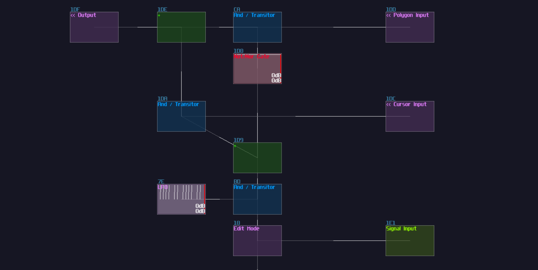
With our final multiplexer, we can now connect our cursor with it. Since the cursor is moved by the location of the currently selected node, we may make use of the data line that tracks the cursor location to move our cursor:
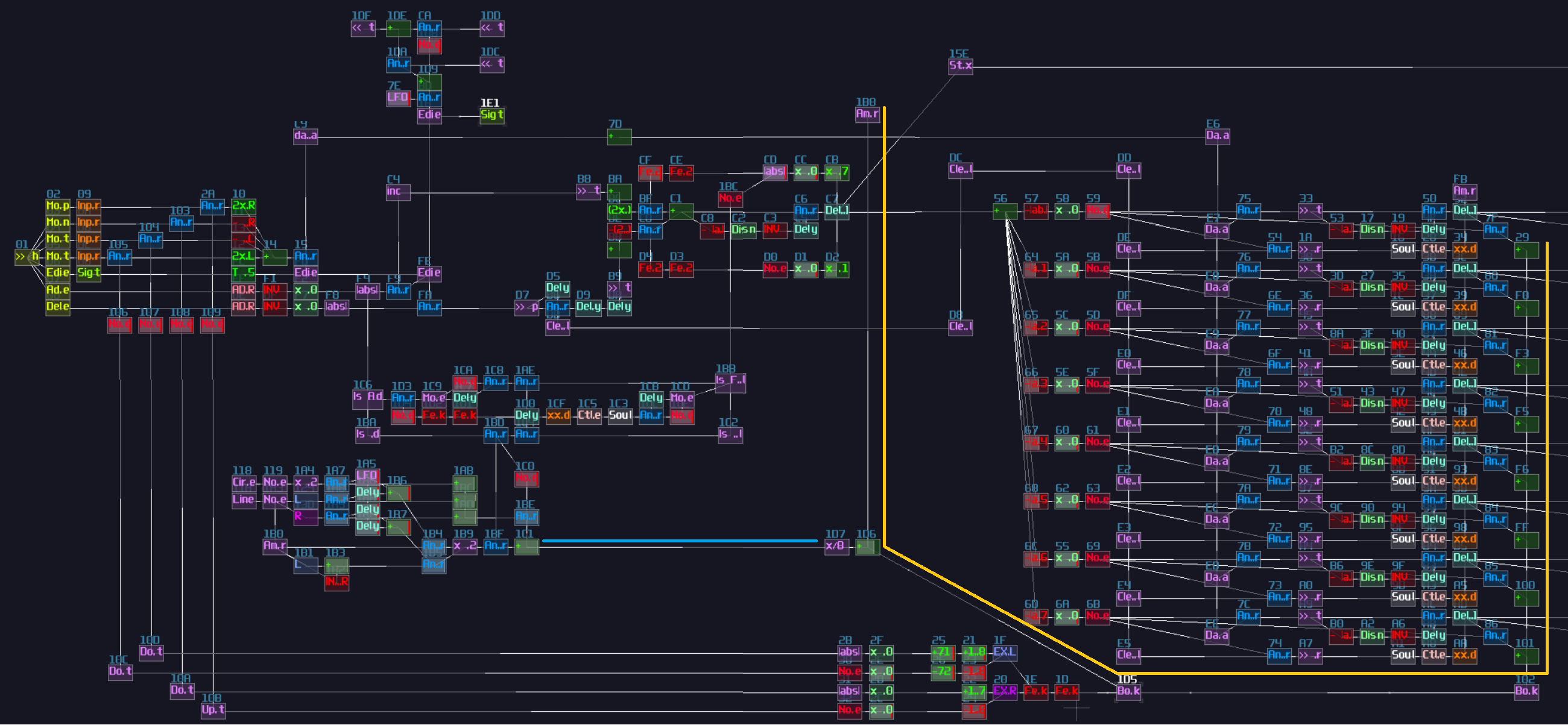
Once you have extended the cursor data line, you can now connect the translated result into the multiplexer, along with the result of the polygon plotter:
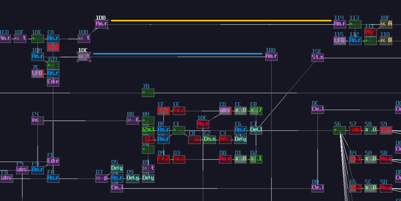
And finally, give it a nice screen next to the controller:
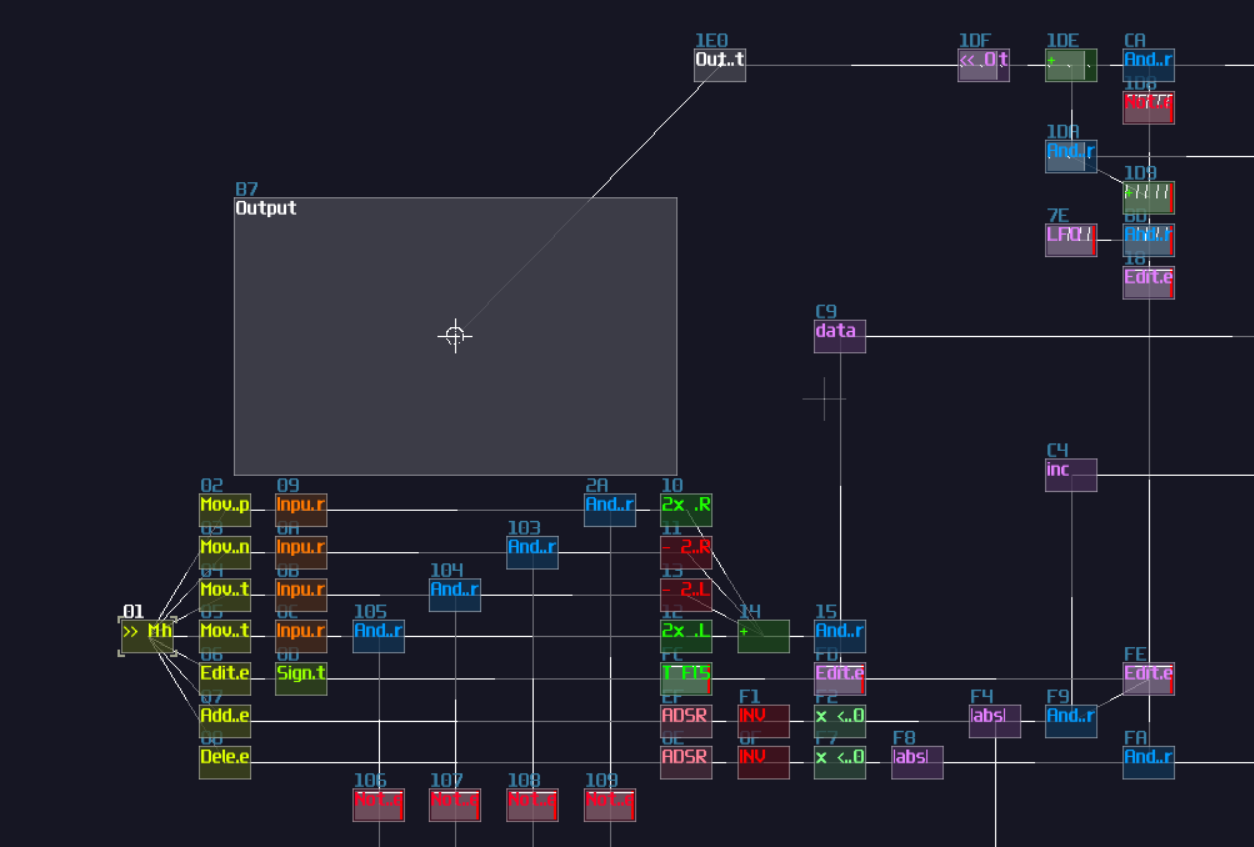
Final Result
With all the things we have done, we can now enjoy the show. Simply pressing a key that corresponds to B5 to toggle the edit mode, we see a cursor which give us a clearer clue where is the current node and its location. We may move around by pressing C5, C#5, D and E for navigation. If we have settle a node, we may press C6 to add another node, and it will form a line; then a triangle, and so on until we hit octagon. If we further press the add button when the shape is an octagon, the contraption refuses to add a new node with temporary showing a cross to notify the users. To remove a node, all we need to do is to press D6, and it removes the most recently added nodes.
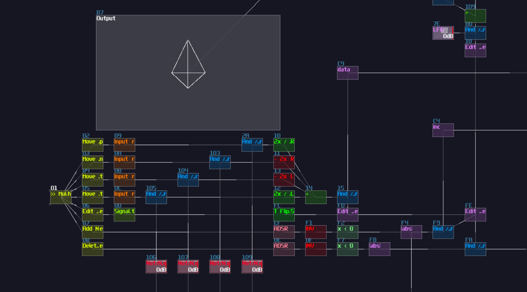
Conclusion
What a journey!!! This is definitely one of the most complicated projects so far in the logbook; in fact, this will be the most complicated chapter because it involves so much elements we have learnt or not in the previous chapters, and this chapter alone has spent me 3 full days from preparation to writing the document, with countless corrections and reworks for certain parts.
This is certainly a chapter I will revise in the future for a better clarity, but hope you can still understand how to build an input interface, a basic memory storage and some hacky tricks!
Example Project:
References
Example 4 - Simple Pie Chart
Testing and Debugging
The last three chapter of the last section might be a bit tricky because you might encounter more problems during more complicated projects, so in the section, let me tell you about some of the common ways to debug the logic stuff, from naive to advance methods.
Audio Response
Null Test
Step Next
DC Signal Debugger
Additional Algorithms in SunVox
Facade Pattern
Facade Pattern
Facade Pattern
Computer Architectures in SunVox
References
These are the generic references that might occur anywhere, and I made the logbook based on these resources since I have learnt these from my bachelor degree and during time I am messing around SunVox.
- [1] Y. N. Patt and S. J. Patel, Introduction to computing systems : from bits and Gates to C and beyond. Boston: Mcgraw-Hill Higher Education, 2004.
- [2] “WarmPlace.ru. SunVox User Manual,” Warmplace.ru, 2024. https://warmplace.ru/soft/sunvox/manual.php (accessed Dec. 02, 2024).